

Overview
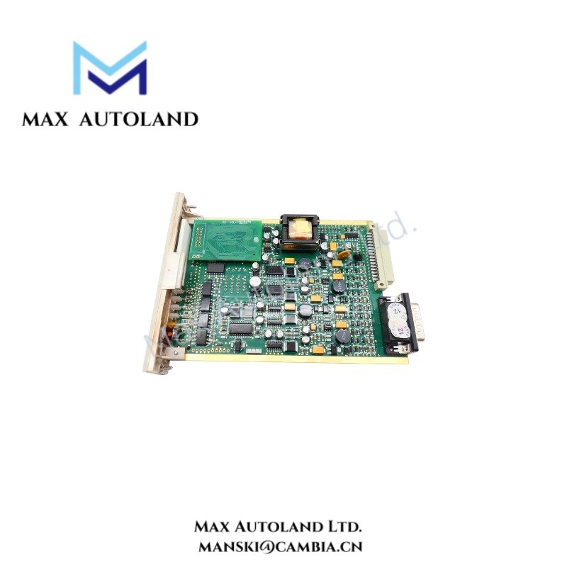
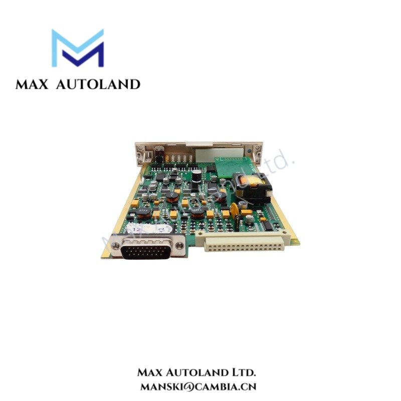
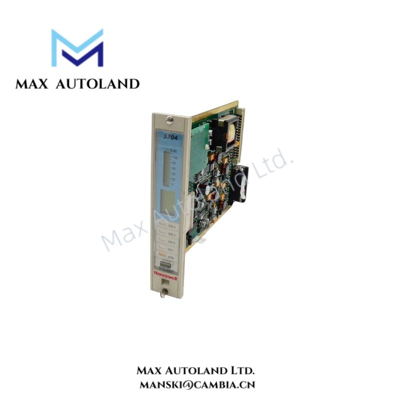
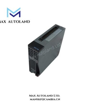
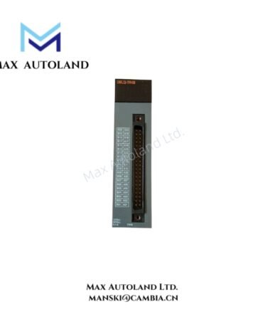
Configured for catalytic gas detector signal processing in the Honeywell 5704 Control System, the Honeywell 05704-A-0144 (05704 Four Channel Control Card Catalytic Input) provides direct electrical execution. The module supports up to four catalytic gas detector inputs with microprocessor-controlled signal conditioning, alarm management, display functions, and configurable operating parameters stored in onboard EEPROM.
Suffix Breakdown & Model Matrix
The supplied documentation identifies 05704-A-0144 as a complete catalog number. No official suffix definition or ordering matrix is specified in the available manufacturer information; therefore, no suffix interpretation is provided.
Hardware Specifications
| Parameter | Specification |
|---|---|
| Model | 05704-A-0144 |
| Brand | Honeywell |
| Product Type | Four Channel Control Card Catalytic Input |
| System Series | Honeywell 5704 Control System |
| Origin | USA |
| Shipping Location | Xiamen, China |
| Dimensions | 2.6 x 17.2 x 12.8 cm |
| Weight | 0.15 kg |
| Operating Voltage | 24 V DC (+/- 10%) |
| Operating Temp | -40 deg C to +70 deg C |
| Humidity | 5 % to 95 % RH (non-condensing) |
| Power Consumption | 8.5 W typical, 12.8 W maximum |
| Supported Channels | 4 catalytic gas detector inputs |
| Analog Interfaces | 4-20 mA, +/- 10 V DC |
| Digital Interfaces | 24 V DC sinking/sourcing |
| Sensor Drive | Constant current |
| Current Adjustment | Electronic, 90 mA to 315 mA in 1 mA increments |
| Maximum Drive Voltage | 10 V |
| Full Scale Signal Range | 15 mV to 300 mV |
| Bridge Voltage | 2 V |
| Bridge Imbalance Limits | +/- 100 mV default |
| Maximum Line Resistance | 40 ohms including sensor at 200 mA |
| Initial Accuracy | +/- 1 % |
| Protection | Short circuit and open circuit protection |
| Fault Detection | Open circuit, short circuit, single bead failure |
| Configuration Storage | EEPROM |
| Front Panel Functions | Backlit display, channel indication, alarm LEDs, reset button, Engineering Card selection |
Channel Isolation and Analog Signal Processing
The control card supports standard industrial analog interfaces including 4-20 mA and +/- 10 V DC while internally processing low-level catalytic bridge signals from 15 mV to 300 mV. Electronic adjustment of bridge balance and signal gain allows detector calibration without mechanical potentiometers. Configuration parameters are retained in EEPROM, allowing operating settings to remain available after power cycling.
Frequently Asked Questions
Q: Does the module require manual potentiometer adjustment for sensor calibration?
A: No. Bridge balance, sensor current, and signal gain are electronically adjustable through the control system configuration.
Q: What detector faults can the control card identify?
A: The module detects open circuit, short circuit, and single catalytic bead failure while monitoring connected detector circuits.
Q: Can configuration settings be retained after power removal?
A: Yes. Operating configuration is stored in onboard EEPROM, allowing settings to remain available after power is restored.
Field Installation Guidelines
- Verify that the supply voltage remains within the specified 24 V DC (+/- 10%) operating range before energizing the control card.
- Confirm detector wiring polarity and conductor continuity before connecting catalytic sensors to the input terminals.
- Route sensor wiring separately from high-power AC cables to reduce induced electrical noise on low-level bridge signals.
- Ground cable shields according to the site grounding philosophy to minimize measurement interference while avoiding ground loops.
- Ensure terminal connections remain within the allowable conductor and torque specifications defined for the control cabinet.
- Perform detector zero and span calibration after installation and after replacement of field sensors or control cards.






Reviews
There are no reviews yet.