


Overview
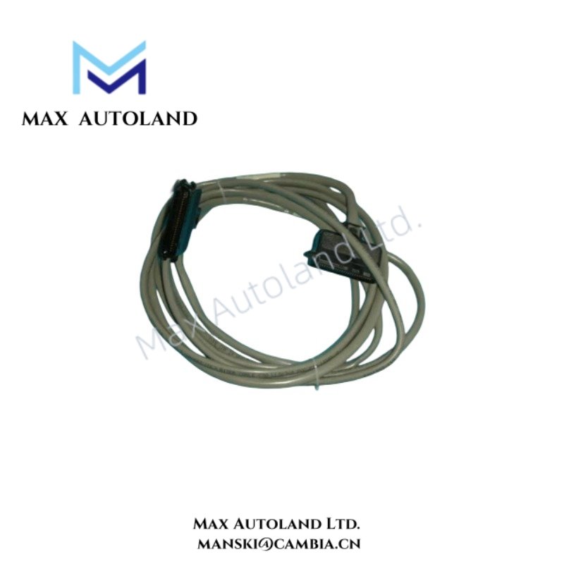
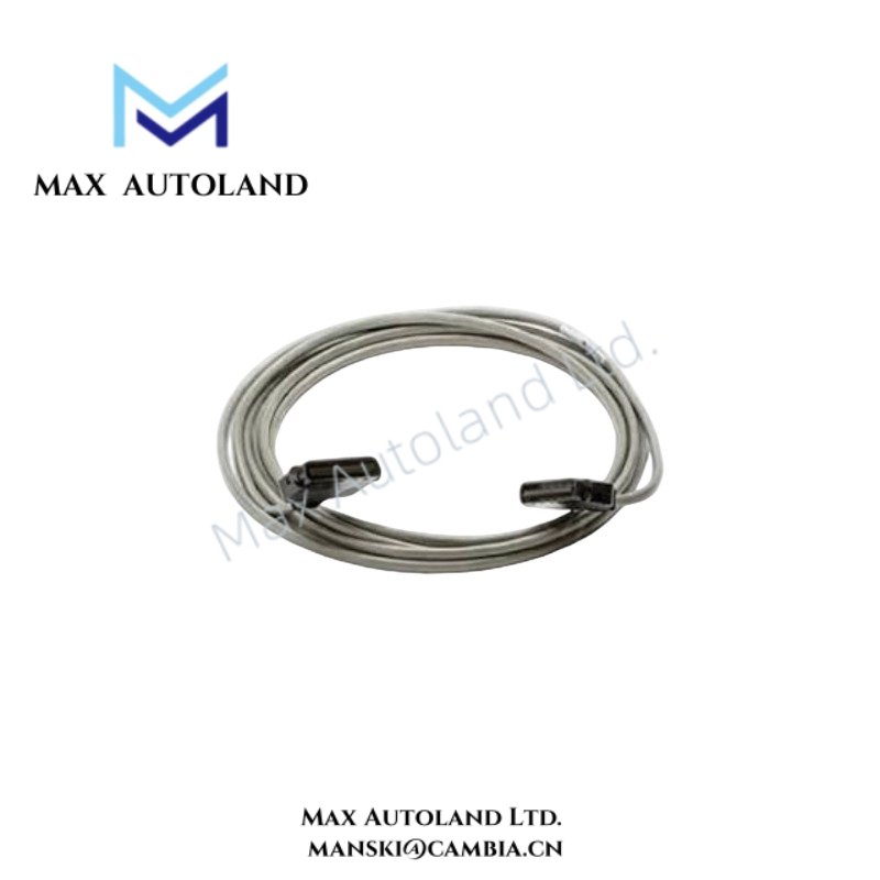
Configured for signal and power interconnection in Honeywell distributed control systems, the Honeywell MU-KFTA08 51201420-008 (MU-KFTA08 FTA I/O Signal Connection Cable) provides direct physical and electrical connection between Field Termination Assemblies and compatible I/O control hardware. The 8 m cable supports analog and digital signal paths and uses multi-core twisted conductors with overall shielding to reduce externally induced electrical interference.
Hardware Specifications
| Parameter | Specification |
|---|---|
| Model | MU-KFTA08 |
| Part Number | 51201420-008 |
| Alternative Part Number Format | 51201420008 |
| Brand | Honeywell |
| Product Type | FTA I/O Signal Connection Cable |
| Compatible Control Systems | Honeywell TDC3000, TPS, Experion PKS DCS |
| Cable Length | 8 m |
| Cable Length | 26.2 ft |
| Supported Signal Types | Analog Inputs/Outputs and Digital Inputs/Outputs |
| Connector Types | High-density D-Sub connectors with locking screws |
| Connector Configuration | Male/female configuration |
| Cable Structure | Multi-core twisted pairs with overall shielding |
| Shielding | Aluminum foil and tinned copper braid |
| Insulation and Jacket Material | Industrial-grade flame-retardant PVC |
| Operating Temp | -40 deg C to +75 deg C |
| Environmental Resistance | Resistant to oil, acids, alkalis, and aging |
| EMI/RFI Suppression | Dual-layer cable shielding |
| Power Consumption | Passive cable assembly; no independent power consumption specified |
Process Signal Transmission and Channel Isolation Practices
The MU-KFTA08 51201420-008 supports physical signal routing between Honeywell FTA hardware and compatible I/O modules. Its twisted-pair conductor arrangement helps control noise pickup on analog and digital circuits, while the foil and tinned copper braid provide an additional shielding path against electromagnetic and radio-frequency interference.
In DCS installations, correct cable routing also supports channel-to-channel signal separation. Keep the cable away from high-current switching conductors, motor feeders, and variable-frequency drive output wiring. In addition, terminate shielding according to the grounding method specified for the associated Honeywell FTA and I/O architecture.
Where connected circuits operate with 4-20 mA HART instrumentation, the cable functions as the physical interconnection path only. HART communication performance depends on the connected I/O hardware, field device configuration, loop impedance, and overall system installation.
Frequently Asked Questions
Q: Can the MU-KFTA08 51201420-008 carry both analog and digital I/O signals?
A: The provided specifications state compatibility with Analog Inputs/Outputs and Digital Inputs/Outputs. The actual signal assignment depends on the connected Honeywell FTA and I/O module configuration.
Q: Does the cable require a separate power supply?
A: No independent cable power consumption is specified. The assembly acts as an interconnection cable, while connected field and I/O circuits provide the required operating power.
Q: Can the MU-KFTA08 cable shielding be connected arbitrarily at both ends?
A: No. Shield termination should follow the grounding and shielding requirements of the connected Honeywell FTA and control system. Incorrect shield termination can create ground-loop or interference problems.
Field Installation Guidelines
- Verify that the full cable designation MU-KFTA08 51201420-008 matches the required Honeywell hardware before installation.
- Isolate or de-energize connected equipment when the applicable system maintenance procedure requires it.
- Align each high-density D-Sub connector carefully before engagement and tighten the locking screws without forcing the connector.
- Do not sharply bend, crush, twist excessively, or mechanically load the cable near connector exits.
- Route the cable separately from motor power cables, high-current conductors, and switching circuits where practical.
- Maintain the cable shielding system according to the grounding requirements of the connected FTA and I/O architecture.
- Inspect connectors and cable jackets for contamination, mechanical damage, corrosion, or insulation deterioration before commissioning.
- After installation, verify signal continuity and confirm correct channel mapping through the associated Honeywell control system configuration.



Reviews
There are no reviews yet.