

Overview
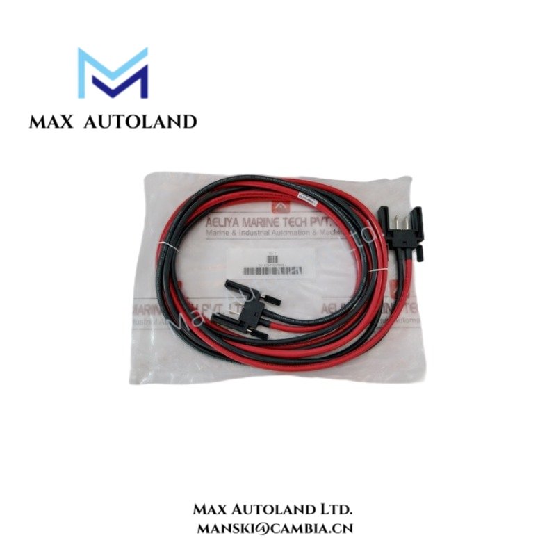
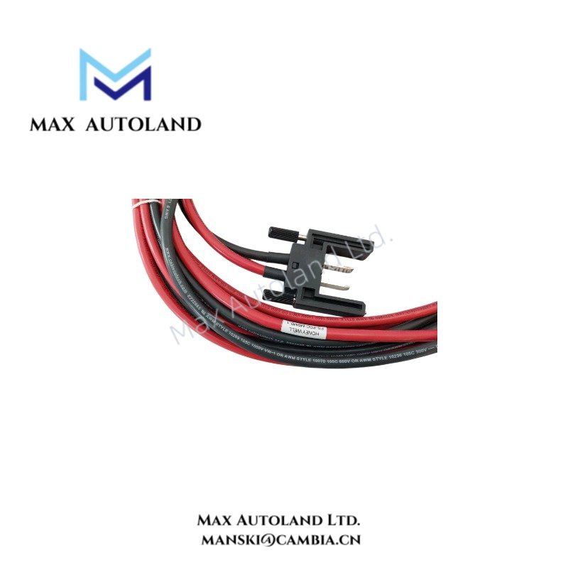
Configured for power transfer between Honeywell power distribution rails, the Honeywell FS-PDC-MBMB-1 (FS-PDC-MBMB-1 Power Distribution Cable) provides a direct electrical connection for 24 VDC or 48 VDC power distribution within compatible control and safety system architectures.
Hardware Specifications
| Parameter | Specification |
|---|---|
| Model | FS-PDC-MBMB-1 |
| Brand | Honeywell |
| Product Type | Power Distribution Cable |
| Power Transfer | 24 VDC / 48 VDC |
| Application | Power transfer between compatible mains power rails |
| Compatible Rail | MB-0001 or equivalent architecture |
| Construction | Industrial control-system power distribution cable |
Power Distribution and DCS Interface Characteristics
The FS-PDC-MBMB-1 carries DC power between compatible power distribution points. The supplied data identifies 24 VDC and 48 VDC operation but does not specify conductor size, connector type, cable length, or current rating.
The cable functions as a passive electrical interconnect. Therefore, it does not perform signal processing, protocol conversion, or controller logic execution.
For Honeywell process-control and safety architectures, the cable should connect only to the designated power interfaces defined by the applicable system documentation. Installers should verify polarity and the permitted supply voltage before energizing the connection.
Frequently Asked Questions
Q: Does the FS-PDC-MBMB-1 consume electrical power?
A: No. The supplied data identifies it as a passive power distribution cable, so it does not have an independent power consumption rating.
Q: What voltage levels does the FS-PDC-MBMB-1 support?
A: The supplied specifications identify 24 VDC and 48 VDC power transfer. The applicable system documentation should determine the permitted voltage for a specific installation.
Q: Does the cable provide communication or protocol conversion?
A: No. Its specified function is DC power transfer between compatible power distribution rails.
Field Installation Guidelines
Verify the cable model and destination interfaces before installation. Confirm the source voltage and polarity against the applicable Honeywell system documentation.
Route the cable separately from low-level analog or communication wiring where practical. Avoid unnecessary parallel runs with high-current switching conductors.
Inspect connectors and cable terminations for contamination, mechanical damage, or loose contacts before energizing the circuit. Secure the cable to prevent excessive bending or mechanical stress at the connection points.
Do not infer conductor capacity, connector pin assignment, cable length, or current limits from the model number. Use the applicable Honeywell installation documentation for these parameters




Reviews
There are no reviews yet.