
Overview
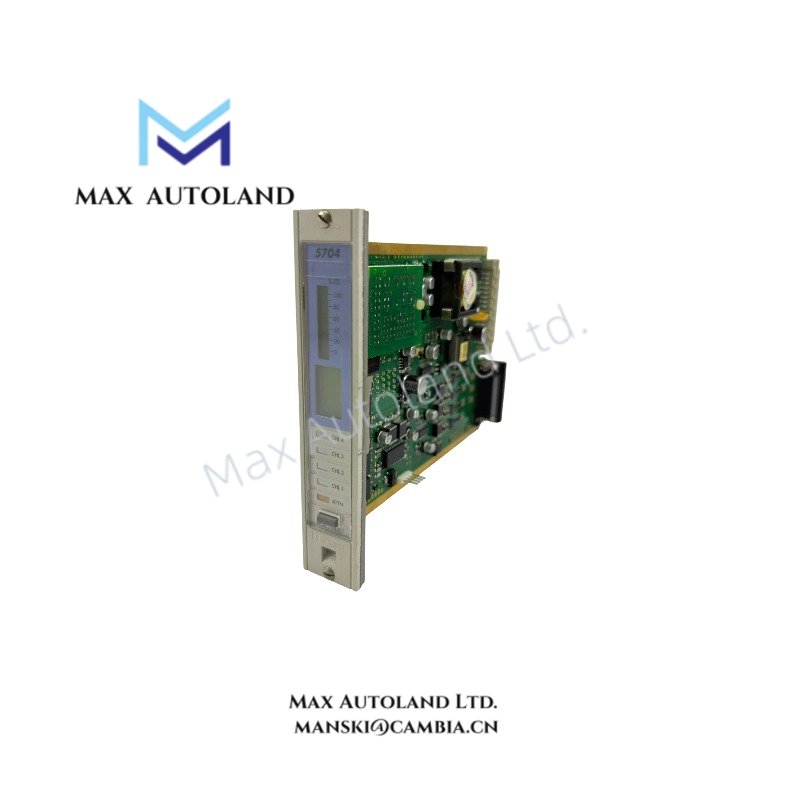
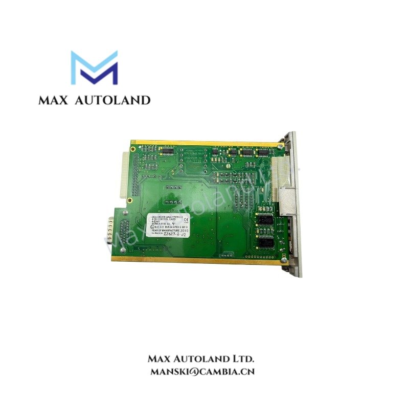
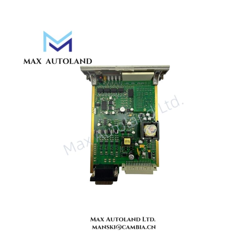
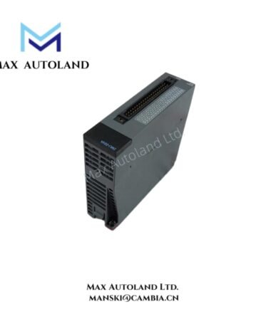
Configured for 4-20 mA gas detector signal processing in the Honeywell 5704 Control System, the Honeywell 05704-A-0145 (05704 Four Channel Control Card) provides direct physical and electrical execution. The 05704-A-0145 supports up to four detector input channels with microprocessor-controlled configuration, alarm handling, local display, and EEPROM-based parameter storage.
Suffix Breakdown & Model Matrix
The supplied documentation identifies a single catalog number 05704-A-0145. No official suffix definition or ordering matrix is specified by the manufacturer documentation; therefore, no suffix interpretation is provided.
Hardware Specifications
| Parameter | Specification |
|---|---|
| Model | 05704-A-0145 |
| Brand | Honeywell |
| Product Type | Four Channel Control Card |
| Series | Honeywell 5704 Control System |
| Origin | USA |
| Place of Shipment | Xiamen, China |
| Dimensions | 2.6 x 17.2 x 12.8 cm |
| Weight | 0.15 kg |
| Operating Temp | -40 degC to +70 degC |
| Humidity | 5 % to 95 % RH, non-condensing |
| Supply Voltage | 24 VDC (+/-10 %) |
| Analog Input | 4-20 mA, +/-10 VDC |
| Digital Input | 24 VDC sinking/sourcing |
| Supported Channels | Up to 4 gas detector channels |
| Measurement Range | 0 to 25 mA linear |
| Maximum Line Resistance | 500 ohms including sensor |
| Configuration | Sensor current source |
| Loop Powered Output | Isolated 24 V +/-5 %, 25 mA maximum |
| Transmitter Supply Output | None |
| Loop Protection | Short circuit protection, open circuit voltage +/-50 V |
| Isolation Breakdown Voltage | Greater than +/-50 VDC to system 0 V |
| Power Consumption | 7.5 W typical, 8.3 W maximum |
| Display | Backlit LCD with channel indication |
| Alarm Indication | Front panel LEDs |
| Configuration Storage | EEPROM |
| Reset Function | Front panel push-button |
Channel-to-Channel Signal Processing
The control card accepts linear 4-20 mA input signals from connected gas detectors and performs independent channel processing under microprocessor control. Configuration parameters are retained in onboard EEPROM, allowing operating settings to remain available after power cycling.
Each measurement channel supports individual status monitoring, alarm indication, and display functions. The isolated loop-powered output supplies up to 25 mA for compatible loop-powered field devices while maintaining electrical separation from the system reference.
Frequently Asked Questions
Q: Does the module support hot swapping while the system remains energized?
A: The supplied technical documentation does not specify hot-swap capability. Module insertion or removal should follow the system maintenance procedure published for the Honeywell 5704 platform.
Q: How are configuration parameters retained after power removal?
A: Operating configuration is stored in onboard EEPROM, allowing user-defined settings to remain available after power restoration.
Q: What sensor signal type is supported by the input channels?
A: The card is designed for current-source sensor configuration with a linear measurement range of 0 to 25 mA and supports standard 4-20 mA gas detector inputs.
Field Installation Guidelines
- Verify the supply voltage is within the specified 24 VDC (+/-10 %) range before energizing the module.
- Confirm field wiring polarity before connecting detector loops.
- Route analog signal wiring separately from high-voltage or high-current conductors to reduce conducted electrical noise.
- Terminate cable shields according to the site’s grounding practice to minimize interference.
- Verify total loop resistance does not exceed the specified maximum value, including field cable and detector resistance.
- Confirm terminal tightening and backplane seating before applying system power.
- Perform functional alarm and input verification after installation and before returning the system to service.





Reviews
There are no reviews yet.