
Overview
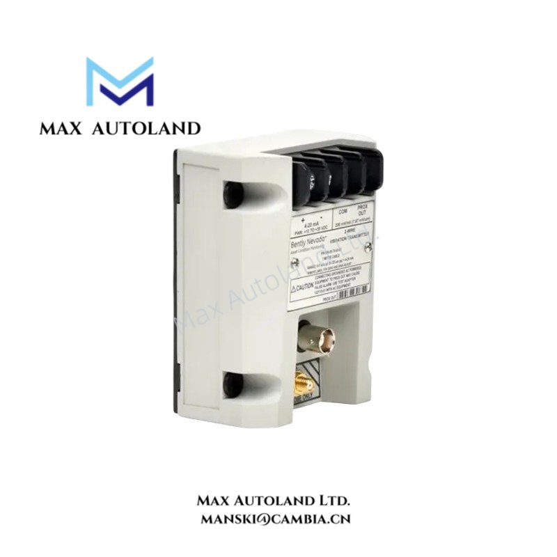
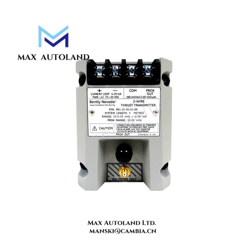
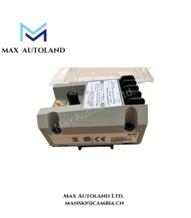
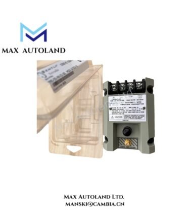
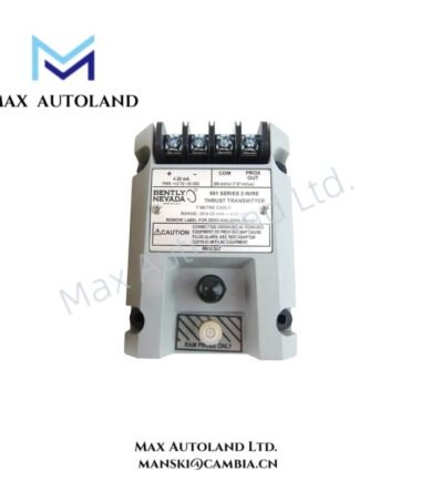
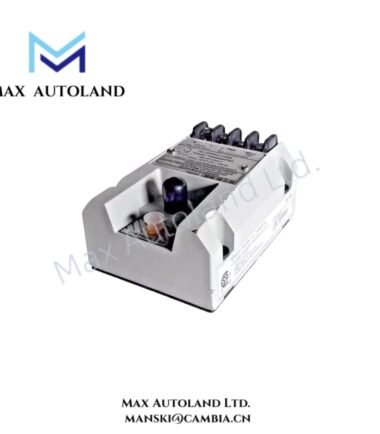
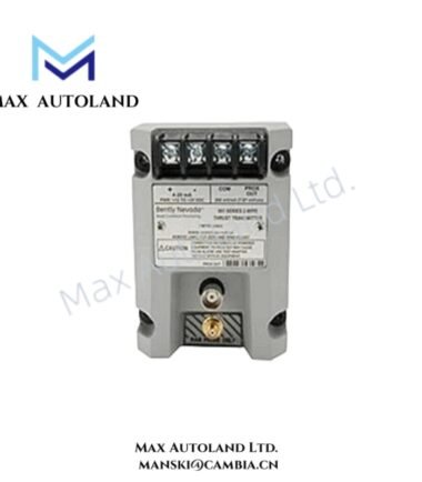
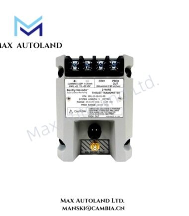
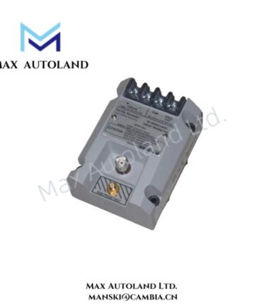
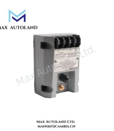
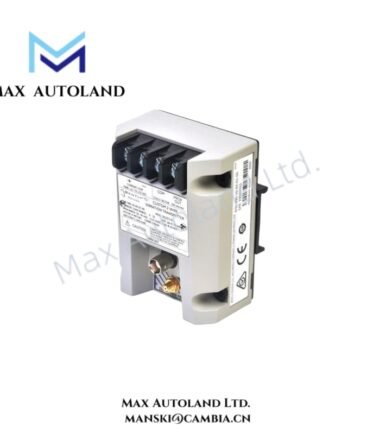
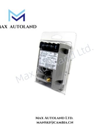
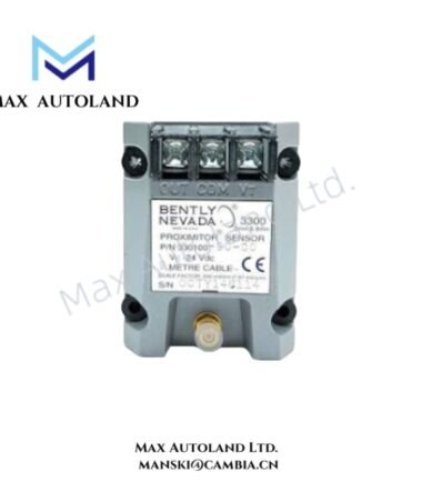
Configured for axial shaft displacement measurement in a thrust monitoring loop, the Bently Nevada 991-06-50-01-CN (991 Thrust Transmitter) converts the probe gap signal into a proportional 4-20 mA output for connection to a DCS or PLC input.
Hardware Specifications
| Parameter | Specification |
|---|---|
| Model | 991-06-50-01-CN |
| Brand | Bently Nevada (Baker Hughes) |
| Product Type | 991 Thrust Transmitter |
| Origin | United States (USA) |
| Power Consumption | Loop-powered; specific consumption not specified |
| Configuration | 2-wire transmitter |
| Measurement | Axial shaft displacement / thrust position |
| Full-Scale Range (-06) | 0.6 – 0 – 0.6 mm |
| Output Signal | Proportional 4-20 mA |
| System Length (-50) | 5.0 m total system length calibration |
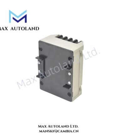
| Mounting (-01) | 35 mm DIN-rail clips |
| Approvals (-CN) | ATEX, IECEx, and China NEPSI |
| Field Supply | 24 VDC field circuit |
Eddy-Current Probe Scaling and Gap Signal
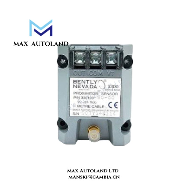
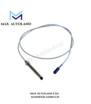
The 991 transmitter operates with a non-contacting eddy-current proximity probe. The probe detects the axial position of the conductive shaft target through the probe-to-target gap. The transmitter then scales this input according to the configured measurement range.
For the 991-06-50-01-CN, the specified range is 0.6 – 0 – 0.6 mm. The transmitter represents the resulting thrust position through a proportional 4-20 mA loop signal. Therefore, the receiving DCS or PLC can process the current directly as an analog process variable.
The -50 configuration specifies calibration for a 5.0 m total system length. Installation should therefore maintain the corresponding probe, extension, and transmitter system configuration.
Frequently Asked Questions
Q: What electrical output does the 991-06-50-01-CN provide?
A: It provides a proportional 4-20 mA current-loop output in a 2-wire configuration.
Q: What measurement range does the -06 option specify?
A: The -06 option specifies a 0.6 – 0 – 0.6 mm axial displacement range.
Q: What mounting arrangement does the -01 option provide?
A: The -01 option specifies pre-installed clips for mounting on a 35 mm DIN rail.
Field Installation Guidelines
- Install the transmitter on a compatible 35 mm DIN rail when using the specified -01 mounting option.
- Connect the transmitter to the matching eddy-current probe and associated system components according to the configured system length.
- Route the probe signal wiring separately from high-current power conductors and switching circuits where practical.
- Use appropriate cable shielding and terminate the shield according to the site instrumentation grounding scheme.
- Verify the loop polarity before applying the field supply.
- Confirm the probe-to-target mechanical gap and transmitter calibration before placing the thrust signal into service.
- Check the 4-20 mA loop at the receiving DCS or PLC input and confirm that the indicated displacement corresponds with the expected mechanical position.
- For hazardous-area installations, maintain the applicable ATEX, IECEx, and China NEPSI installation requirements for the complete measurement loop.
Reviews
There are no reviews yet.