

Overview
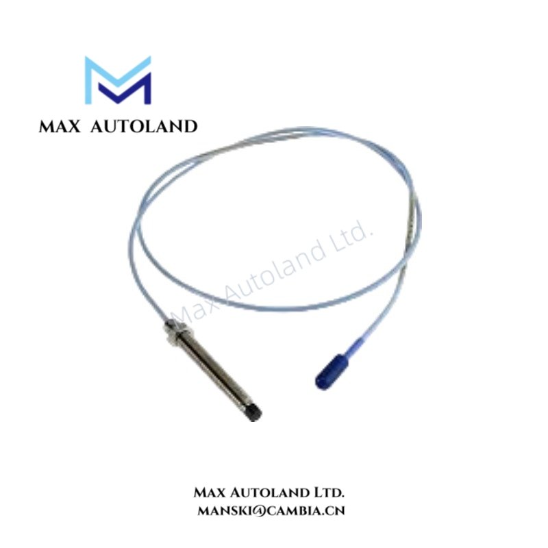
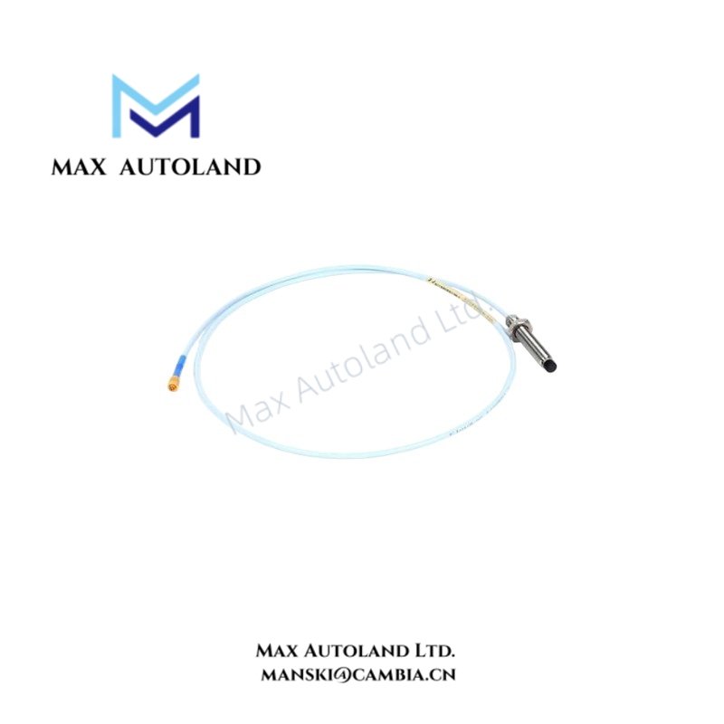
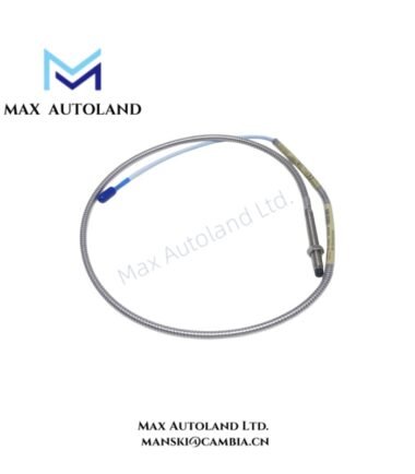
Configured for non-contact measurement of conductive-target position in a 3300 XL 8 mm proximity transducer system, the Bently Nevada 330103-08-13-10-02-05 (330103 Eight Millimeter Proximity Probe) provides the physical sensing element for static position and dynamic vibration measurements. The probe uses an M10 x 1 case thread, an 80 mm unthreaded section, a 130 mm overall case length, and a 1 m total probe length.
Hardware Specifications
| Parameter | Specification |
|---|---|
| Model | 330103-08-13-10-02-05 |
| Base Model | 330103 |
| Brand | Bently Nevada |
| Product Type | Eight millimeter proximity probe |
| Origin | U.S.A. |
| Dimensions | 80 mm unthreaded length; 130 mm overall case length; 1 m total probe length |
| Operating Temp | -52 to +177 deg C |
| Power Consumption | Not applicable to the passive probe element |
| Probe Mounting | Forward mount |
| Case Thread | M10 x 1 |
| Armor Selection | Without armor |
| Cable and Connector Option | Standard cable without connector protector |
| Agency Approval Option | CSA, ATEX and IECEx option; verify delivered certificate |
| Case Material | AISI 303 or 304 stainless steel |
| Probe Tip Material | Polyphenylene sulfide (PPS) |
| Probe Cable Construction | 75 ohm triaxial cable |
| Probe Cable Insulation | FEP |
| Recommended Mounting Torque | 11.2 N m; 7.5 N m on the first three threads |
| Connector Material | Gold-plated brass or beryllium copper |
| Measurement Principle | Non-contact measurement of conductive-target position |
| Sensing Chain | Probe, matching extension cable, and Proximitor Sensor |
Eddy-Current Probe Scaling and Gap Voltage
The 330103-08-13-10-02-05 operates as the sensing element in an eddy-current proximity measurement chain. The probe detects changes in the distance between its sensing tip and a conductive shaft target. The matching extension cable and Proximitor Sensor establish the electrical characteristics required for the specified measurement range.
During commissioning, the installed probe, extension cable, and Proximitor Sensor should be treated as one calibrated sensing chain. Gap voltage validation provides a practical check of the probe-to-target operating point. A -10 VDC target is commonly used as a reference point in Bently Nevada proximity probe setup procedures, subject to the applicable system calibration and documentation.
The 75 ohm triaxial cable uses FEP insulation. Therefore, cable routing should maintain the specified installation environment and avoid unnecessary proximity to electrical noise sources. The final vibration or position measurement depends on the complete probe and signal-conditioning chain rather than the probe alone.
Frequently Asked Questions
Q: Does the probe require a separate Proximitor Sensor for operation?
A: Yes. The probe forms part of a sensing chain with a matching extension cable and Proximitor Sensor. The supplied probe does not independently provide the conditioned monitoring output.
Q: What mounting thread does the 330103-08-13-10-02-05 use?
A: The case uses an M10 x 1 thread and a forward-mount configuration.
Q: What should be checked before replacing an installed probe?
A: Verify the probe model, thread configuration, cable and connector selection, armor configuration, approval option, and compatibility with the installed extension cable and Proximitor Sensor.
Field Installation Guidelines
- Verify the complete probe model against the installed sensing-chain configuration before installation.
- Confirm the M10 x 1 case thread and forward-mount arrangement match the mechanical mounting point.
- Install the probe without forcing the threaded body or damaging the PPS probe tip.
- Apply the specified mounting torque of 11.2 N m, with 7.5 N m specified on the first three threads.
- Route the triaxial cable away from avoidable sources of electrical interference and mechanical abrasion.
- Maintain the cable insulation and connector surfaces in clean, dry condition during installation.
- Verify the probe-to-target gap according to the applicable 3300 XL system installation and calibration procedure.
- Check the gap voltage after installation when the measurement chain requires this validation.
- Confirm the extension cable and Proximitor Sensor match the probe configuration before energizing the monitoring channel.
- For CSA, ATEX, or IECEx installations, verify the delivered approval documentation and apply the applicable installation requirements.




Reviews
There are no reviews yet.