
Overview
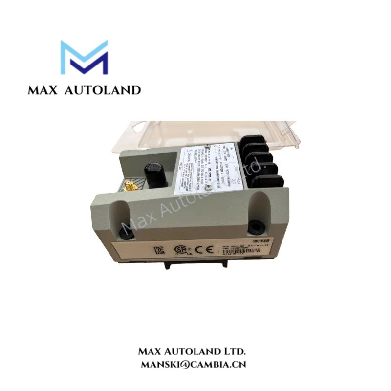
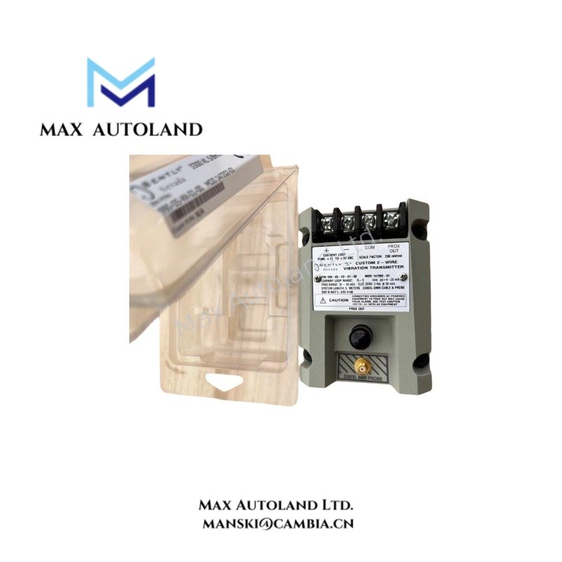
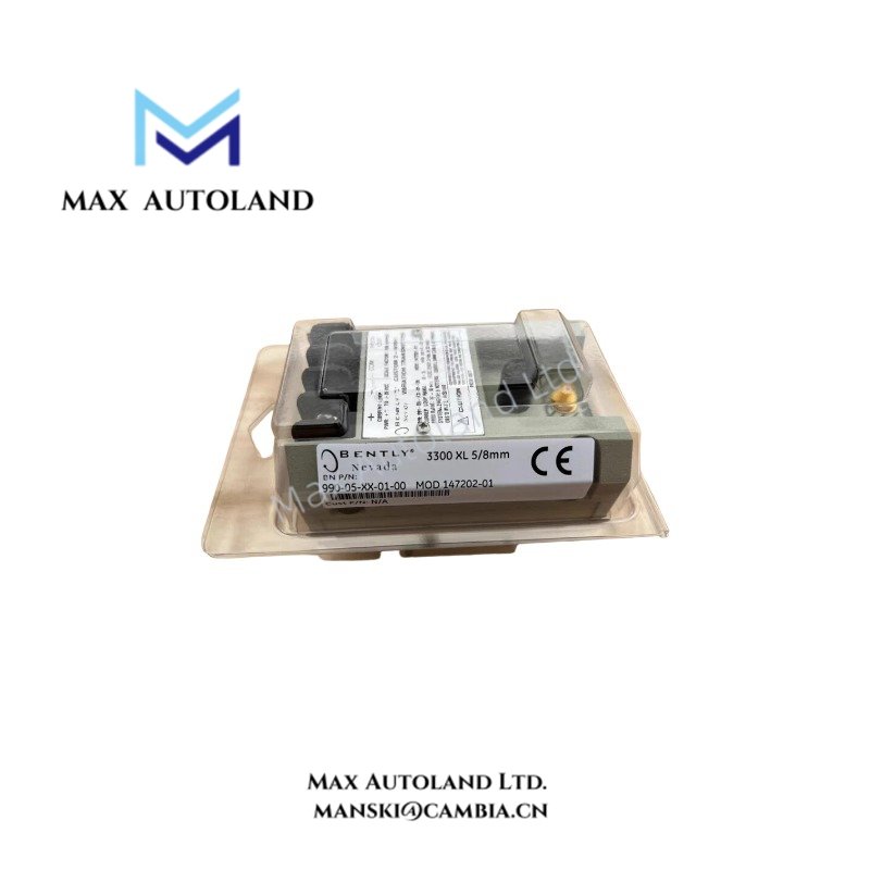
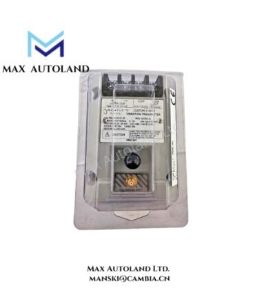
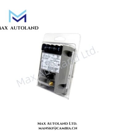
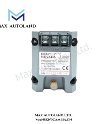
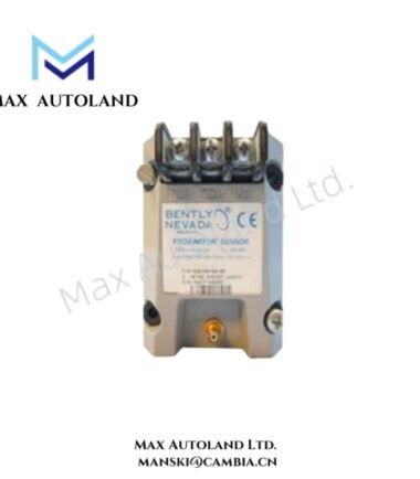
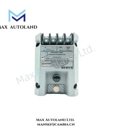
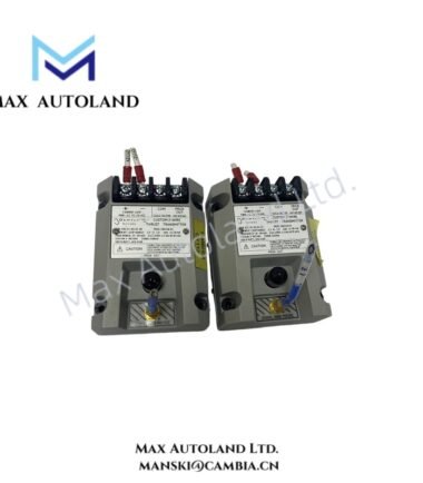
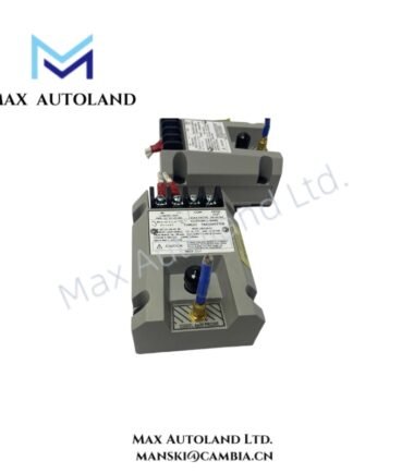
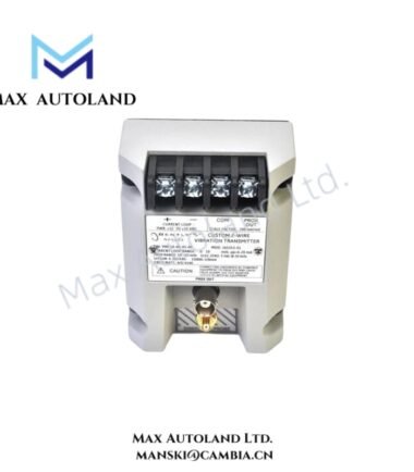
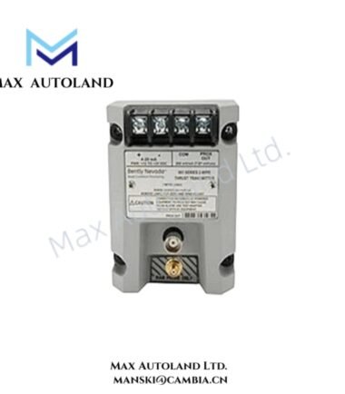
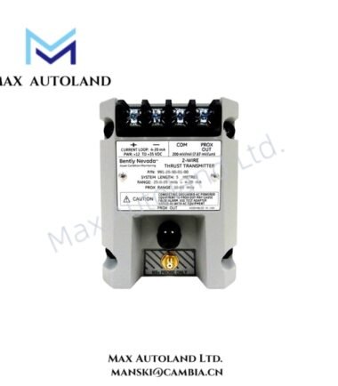
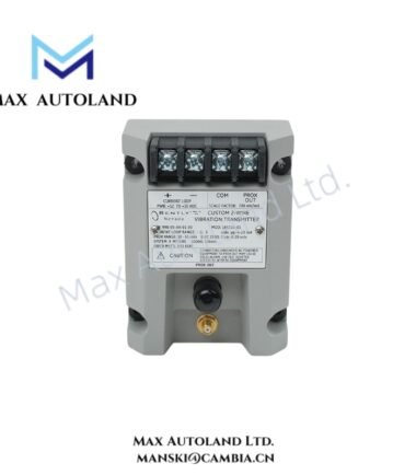
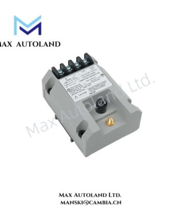
Configured for overall shaft vibration measurement in the 990 transmitter system, the Bently Nevada 990-05-XX-01-00 MOD: 289549-17 (990-05-XX-01-00 vibration transmitter) converts a compatible proximity probe signal into a 4-20 mA two-wire current-loop output. Internal Proximitor circuitry provides signal conditioning without a separate external Proximitor Sensor.
Hardware Specifications
| Parameter | Specification |
|---|---|
| Model | 990-05-XX-01-00 MOD: 289549-17 |
| Brand | Bently Nevada |
| Product Type | 990 two-wire vibration loop transmitter |
| Measurement Range | 0-5 mils peak-to-peak (0-125 micrometres) |
| Measurement Input | Compatible 3300 NSv proximity transducer system |
| Measurement Output | 4-20 mA two-wire current loop |
| Terminal Supply | +12 to +35 VDC |
| Maximum Loop Resistance | 1000 ohm at 35 VDC |
| Typical Current Limit | 23 mA |
| Not-OK Output | Less than 3.6 mA |
| Buffered Probe Output | PROX OUT, not electrically isolated |
| Signal Conditioning | Internal Proximitor circuitry |
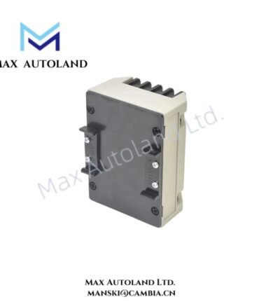
| Mounting | 35 mm DIN rail clips |
| Approval Option | 00; not requested |
| System Length | XX; exact value not specified |
Eddy-Current Signal Processing
The 990 transmitter receives the proximity transducer signal and conditions the measured shaft displacement for current-loop transmission. The configured measurement range is 0-5 mils peak-to-peak, equivalent to 0-125 micrometres. The internal Proximitor circuitry eliminates the requirement for a separate external Proximitor Sensor.
The transmitter provides a 4-20 mA output for connection to a control or monitoring system. The PROX OUT terminal provides a buffered probe signal, but the supplied data specifies that this output is not electrically isolated.
Frequently Asked Questions
Q: What type of output does the 990-05-XX-01-00 provide?
A: It provides a 4-20 mA two-wire current-loop output proportional to the configured overall peak-to-peak vibration range.
Q: What supply voltage does the transmitter require?
A: The specified terminal supply range is +12 to +35 VDC. The maximum specified loop resistance is 1000 ohm at 35 VDC.
Q: Can the transmitter operate with any 3300 NSv probe system?
A: The supplied data identifies the 3300 NSv family as compatible and states that the matched system length is required. The XX system-length field remains unspecified for this particular unit.
Field Installation Guidelines
Install the transmitter using the supplied 35 mm DIN rail clips and maintain secure mechanical engagement with the rail.
Connect the two-wire current loop according to the transmitter terminal designation. Confirm that the available DC supply and total loop resistance remain within the specified limits.
Route the proximity probe wiring separately from high-current power conductors and switching circuits where practical. Maintain the probe signal wiring according to the applicable Bently Nevada installation requirements.
Connect cable shields according to the site grounding scheme and avoid creating unintended ground loops. The PROX OUT connection is not electrically isolated, so the receiving equipment must account for the electrical relationship between this output and the transmitter circuit.
Before commissioning, verify the selected 0-5 mils peak-to-peak range, probe compatibility, system length, loop polarity, supply voltage, and signal response. The supplied data does not establish the exact XX system-length code, so this field should be confirmed against the installed probe and cable configuration.
Reviews
There are no reviews yet.