
Overview
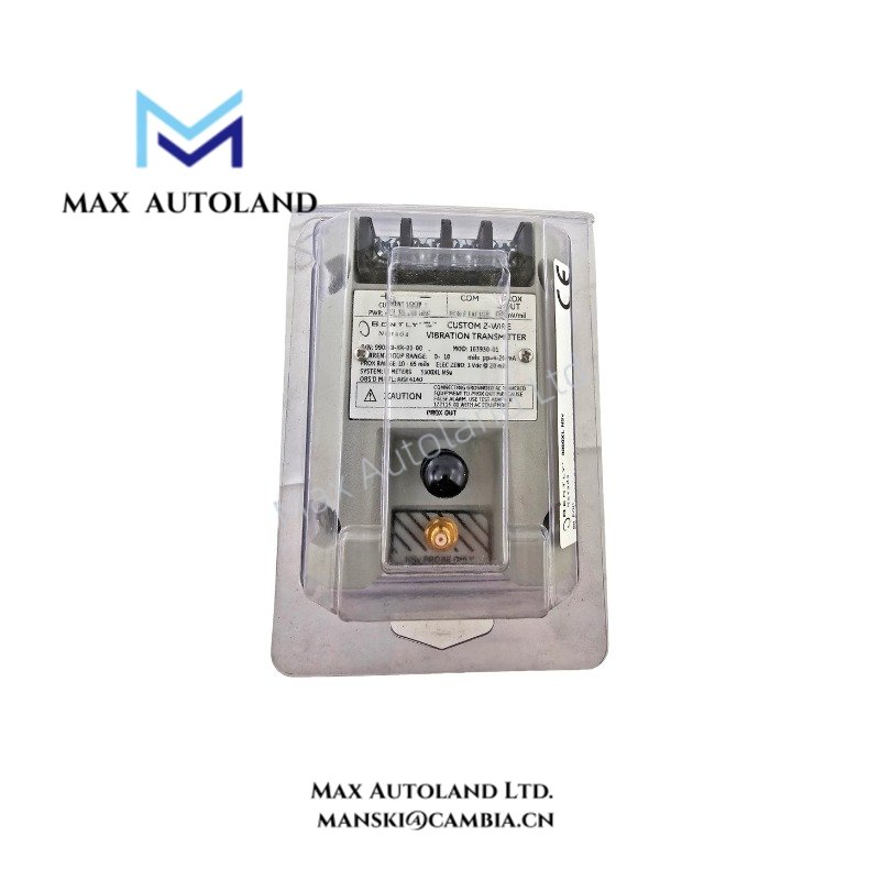
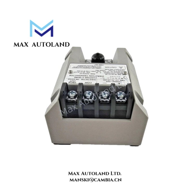
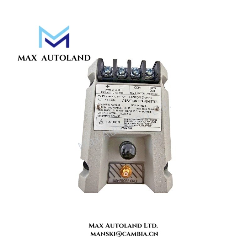
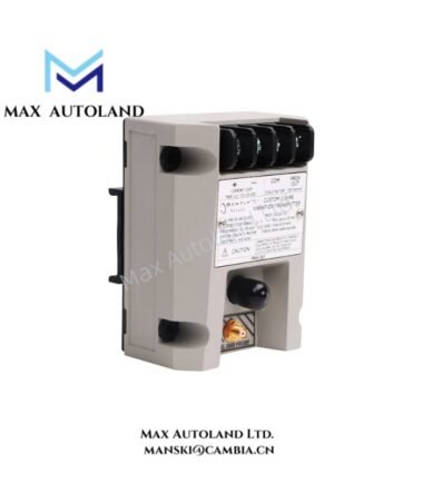
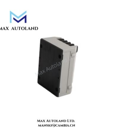
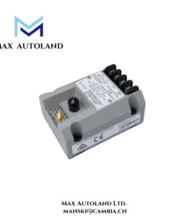
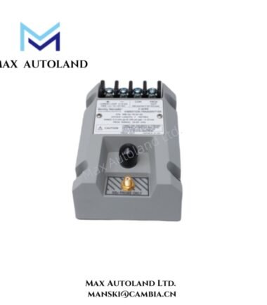
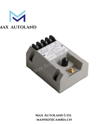
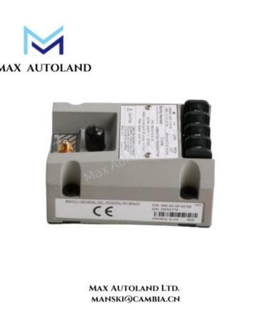
Configured for converting a compatible proximity-probe signal into a proportional vibration current output, the Bently Nevada 990-10-XX-01-00 MOD 163930-01 (990-10-XX-01-00 vibration measurement transmitter) provides two-wire signal conditioning for a machinery-control loop. The transmitter accepts a 3300 NSv probe and matching extension cable and outputs 4-20 mAdc.
Hardware Specifications
| Parameter | Specification |
|---|---|
| Model | 990-10-XX-01-00 MOD 163930-01 |
| Brand | Bently Nevada |
| Product Type | Vibration Measurement Transmitter |
| Standard Transducer Input | One 3300 NSv probe and matching extension cable |
| Signal Output | 4-20 mAdc, two-wire loop |
| Transmitter Supply | +12 to +35 Vdc at transmitter terminals |
| Maximum Loop Resistance | 1000 ohm including cable at 35 Vdc |
| Typical Current Limiting | 23 mA |
| Zero and Span | Non-interacting external adjustments |
| Not OK Output | Less than 3.6 mA within 100 microseconds |
| Not OK Recovery | 2-3 seconds after fault removal |
| Operating Temp | -35 to +85 deg C |
| Storage Temp | -52 to +100 deg C |
| Diagnostic Lead Limit | 3 m from Proximitor output BNC connector |
Eddy-Current Probe Scaling and Gap Validation
The 990-10-XX-01-00 MOD 163930-01 processes the signal from a compatible 3300 NSv proximity transducer system. Therefore, the probe, extension cable, and transmitter configuration must remain electrically compatible.
The installed probe system establishes the measurement scaling. In addition, the Proximitor signal provides the physical gap information required by the transmitter input. During commissioning, verify the probe-system calibration and gap voltage against the installed transducer assembly before applying the current-loop output to control or protection logic.
The transmitter provides a conditioned 4-20 mAdc signal to the receiving system. The receiving control or protection system interprets this current signal; the transmitter itself does not constitute a complete machinery diagnostic or protection system.
Frequently Asked Questions
Q: What transducer assembly does the transmitter accept?
A: The specified input consists of one 3300 NSv probe and its matching extension cable. Verify compatibility with the installed transmitter configuration before replacement.
Q: What happens when the transmitter detects a NOT OK condition?
A: The transmitter drives the output below 3.6 mA within 100 microseconds. After fault removal, the specified recovery time is 2-3 seconds.
Q: What is the maximum diagnostic lead length?
A: The diagnostic lead must not exceed 3 m from the Proximitor output BNC connector.
Field Installation Guidelines
- Verify the complete probe, extension cable, and transmitter assembly before installation.
- Confirm the selected measurement range and calibrated probe-system length against the installed machinery instrumentation.
- Install the transmitter within the specified operating temperature range of -35 to +85 deg C.
- Maintain the diagnostic lead within the specified 3 m limit from the Proximitor output BNC connector.
- Route the vibration signal wiring separately from high-current switching and other strong electromagnetic-noise sources.
- Use appropriate cable shielding and grounding practices for the installed machinery monitoring system.
- Verify the transmitter supply at its terminals and confirm that the loop resistance remains within the 1000 ohm maximum at 35 Vdc.
- Check the 4-20 mAdc output against the receiving control or protection input before placing the loop into service.
- Confirm the NOT OK response and recovery behavior during commissioning where the system test procedure permits.
- Do not substitute a probe or extension cable without confirming compatibility with the transmitter configuration.





Reviews
There are no reviews yet.