
Overview
Hardware Specifications
| Parameter | Specification |
|---|---|
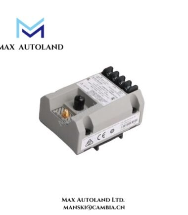
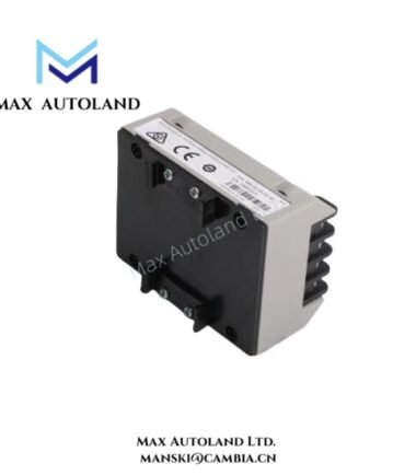
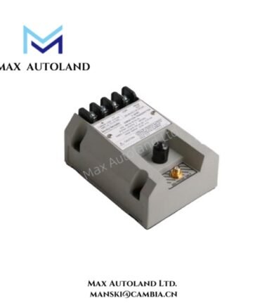
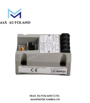
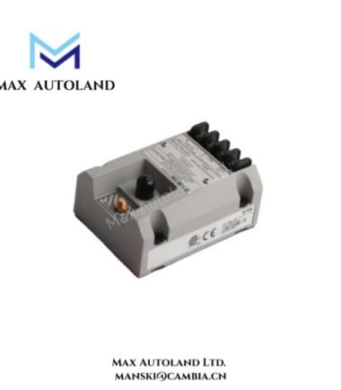
| Model | 990-04-XX-03-00 |
| Brand | Bently Nevada |
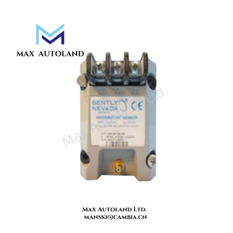
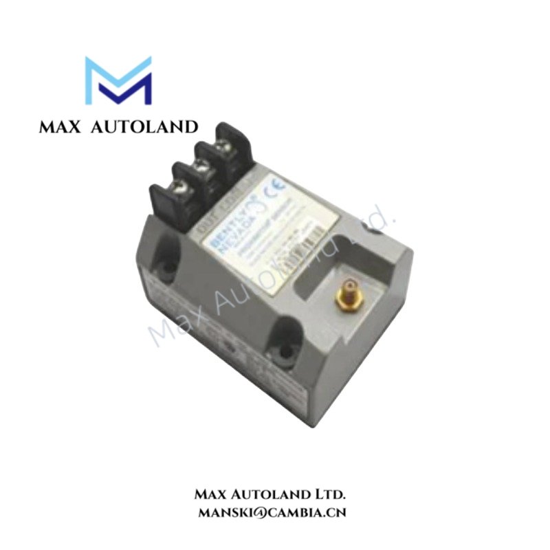
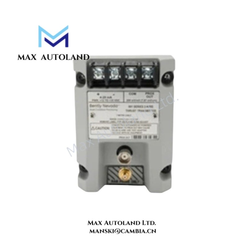
| Product Type | Vibration Transmitter |
| Measurement Range | 0-4 mils peak-to-peak |
| Input | One compatible 3300 NSv proximity probe and extension cable |
| Output Signal | 4-20 mA DC, two-wire loop-powered |
| Supply Voltage | +12 to +35 VDC at transmitter terminals |
| Maximum Loop Resistance | 1,000 ohms, including cable, at 35 VDC |
| Current Limiting | 23 mA typical |
| Probe Gap | 0.5-1.75 mm (20-55 mils) |
| Diagnostic Output | Non-isolated PROX OUT and COM terminals, plus coaxial connector |
| PROX OUT Impedance | 10 kohms, calibrated for a 10 Mohm load |
| PROX OUT Linear Range | 1.4 mm (55 mils), beginning approximately 0.25 mm (10 mils) from the target |
| PROX OUT Incremental Scale Factor | 7.87 mV/um (200 mV/mil) +/-6.5% typical; +/-10% worst case |
| Typical PROX OUT Noise | 50 mV peak-to-peak |
| Frequency Response | 5 Hz to 6,000 Hz, +0/-3 dB |
| Minimum Target Size | 9.5 mm (0.375 in) diameter |
| Zero and Span Adjustment | External, non-interacting potentiometers |
| Not OK / Signal Defeat | Output falls below 3.6 mA within 100 us of a Not OK condition |
| Signal Recovery | Within 2-3 seconds after the Not OK condition clears |
| Power-Up Inhibit | Output remains below 3.6 mA for 2-3 seconds after power is applied |
| System Length Option | XX: 5.0 m or 7.0 m, depending on the ordered configuration |
| Mounting Option | DIN rail clips and screws |
| Agency Approval Option | 00: No agency approval required |
| Transmitter Operating Temperature | -35 to +85 deg C (-31 to +185 deg F) |
| Transmitter Storage Temperature | -52 to +100 deg C (-62 to +212 deg F) |
| Probe Operating Temperature | -52 to +177 deg C (-62 to +351 deg F) |
| Probe Storage Temperature | -52 to +177 deg C (-62 to +351 deg F) |
| Transmitter Weight | 0.43 kg (0.9 lbm) |
| Typical Total System Weight | 0.82 kg (1.8 lbm) |
Configuration and Ordering Details
The ordering code identifies the measurement range, system cable length, mounting arrangement, and agency approval requirements.
| Code Position | Selected Code | Configuration |
|---|---|---|
| A – Full-Scale Option | 04 | 0-4 mils peak-to-peak (0-100 um peak-to-peak) |
| B – System Length Option | XX | Must be confirmed as 50 (5.0 m) or 70 (7.0 m) |
| C – Mounting Option | 03 | DIN rail clips and screws |
| D – Agency Approval Option | 00 | Agency approval not required |
Ordering note: The supplied ordering guide does not define XX as a valid system length code. Confirm the complete part number against the equipment nameplate or ordering documentation before purchase.
Signal Operation and Diagnostics
The transmitter conditions the proximity probe signal and converts vibration amplitude into a proportional 4-20 mA output for a machinery control system. The receiving system can use this signal for vibration indication, alarm processing, and protection logic according to its configured limits.
The integrated Proximitor sensor also provides a separate diagnostic signal through the PROX OUT and COM terminals and the coaxial connector. This output allows technicians to examine dynamic vibration and probe gap voltage. The diagnostic output is non-isolated, so grounded, AC-powered test equipment requires the 122115-01 Test Adapter for signal isolation.
Installation and Operating Conditions
Set the probe gap between 0.5 and 1.75 mm (20 and 55 mils) from the target to maintain the specified full-scale measurement range. The maximum loop resistance is 1,000 ohms at a 35 VDC supply, including cable resistance. Check the receiving circuit resistance and supply voltage together before commissioning.
The transmitter’s Not OK / Signal Defeat circuit drives the output below 3.6 mA when a qualifying probe or connection fault occurs. The output returns to normal operation within 2-3 seconds after the fault clears. At startup, the same low-current state indicates that the transmitter is not yet ready.
Frequently Asked Questions
Q: What does the 990-04 configuration mean?
A: The 04 code selects a 0-4 mils peak-to-peak (0-100 um peak-to-peak) full-scale vibration range. The 03 code specifies DIN rail clips and screws, while 00 indicates that agency approval is not required.
Q: Which proximity probe system does this transmitter accept?
A: It accepts one compatible Bently Nevada 3300 NSv proximity probe and its matching extension cable. Confirm the required system length and the complete probe-cable configuration before ordering.
Q: What happens when the transmitter detects a Not OK condition?
A: The 4-20 mA output falls below 3.6 mA within 100 us after the condition occurs. Once the condition clears, the output recovers within 2-3 seconds.
Q: Can I use the PROX OUT signal for diagnostic measurements?
A: Yes. PROX OUT provides a dynamic vibration and gap voltage signal. Use compatible ungrounded portable test equipment, or the 122115-01 Test Adapter when using grounded, AC-powered test equipment.




Reviews
There are no reviews yet.