


Overview
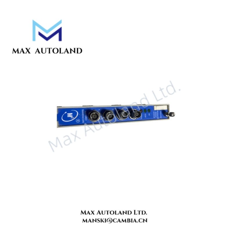
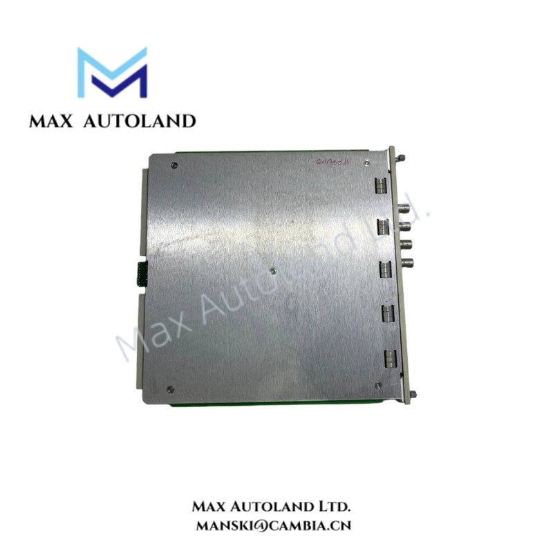
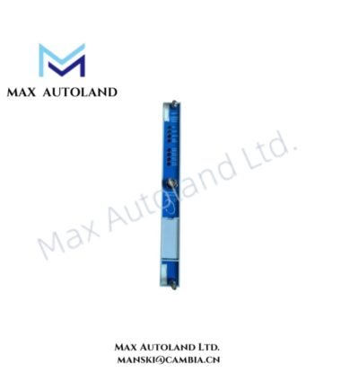
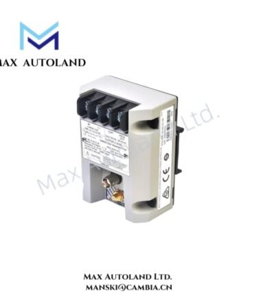
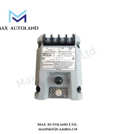
Configured for four-channel vibration and position monitoring in the Bently Nevada 3500 Series Machinery Protection System, the Bently Nevada 3500/42M-01-05 (3500/42M Proximitor/Seismic Monitor Module) conditions proximity and seismic transducer signals, calculates programmable measurements, and compares measured values with Alert and Danger setpoints.
Suffix Breakdown & Model Matrix
| Model Element | Specification |
|---|---|
| Base Model | 3500/42M |
| Module Type | Proximitor/Seismic Monitor Module |
| Channel Capacity | 4 channels |
| Option 01 | Proximitor/Seismic I/O Module with internal terminations |
| Option 05 | Hazardous Area Approval package |
| Hazardous Area Certifications | ATEX, IECEx, CSA Class I, Zone 2, as applicable to the approved configuration |
Hardware Specifications
| Parameter | Specification |
|---|---|
| Model | Bently Nevada 3500/42M-01-05 |
| Brand | Bently Nevada |
| Operating Temp | -30 deg C to +65 deg C |
| Storage Temp | -40 deg C to +85 deg C |
| Relative Humidity | Up to 95%, non-condensing |
| Power Consumption | Not specified in supplied data |
| Channels | 4 |
| Input Types | Proximity, velocity, or acceleration transducers |
| Input Impedance | 10 kOhm for standard Proximitor and acceleration inputs |
| Transducer Power Supply | -24 VDC |
| Static Value Resolution | 0.3662 microampere per bit |
| Measurement Accuracy | +/- 0.33% of full scale typical; +/- 1% maximum, excluding filters |
| Measurement Update Rate | Approximately 100 ms |
| Recorder Output | +4 to +20 mA proportional to monitor full scale |
| Recorder Output Load | 0 to 600 ohm |
| Buffered Output | One front-panel coaxial connector per channel |
| Buffered Output Protection | Short-circuit protected |
| Programmable Measurements | Radial vibration, thrust position, differential expansion, eccentricity, REBAM, acceleration, velocity, shaft absolute, circular acceptance region |
| System | 3500 Series Machinery Protection System |
Eddy-Current Probe Scaling and Rotor Signal Processing
The 3500/42M accepts proximity transducer signals for machinery vibration and position measurements. The monitor conditions the incoming signals before calculating the selected measurement.
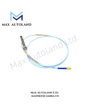
For eddy-current probe applications, technicians should verify probe scaling and electrical gap conditions against the applicable transducer configuration. A nominal -10 VDC target commonly provides a reference point for Bently Nevada proximity probe gap validation, although the applicable target depends on the specific probe and installation.
Furthermore, technicians should evaluate probe orientation, shaft target geometry, cable routing, and signal separation when installing multiple channels. These factors affect the measured rotor-dynamic signal and can introduce unwanted cross-channel interference.
Frequently Asked Questions (FAQ)
Q: How many transducer channels does the 3500/42M-01-05 provide?
A: The module provides four independent channels and accepts proximity, velocity, or acceleration transducer inputs according to the configured measurement function.
Q: What recorder output does the module provide?
A: Each configured recorder output provides +4 to +20 mA proportional to monitor full scale and supports a stated load range of 0 to 600 ohm.
Q: Does Option 05 define the module’s measurement function?
A: No. Option 05 identifies the hazardous-area approval package. The measurement functions depend on the 3500/42M configuration and selected transducer inputs.
Field Installation Guidelines
- Install the monitor in the specified 3500 Series rack position and follow the rack wiring documentation.
- Confirm the I/O module configuration before connecting field wiring.
- Verify proximity probe polarity, cable identification, and transducer compatibility before energizing the channel.
- Route transducer signal cables separately from high-voltage power and high-current switching conductors.
- Maintain appropriate shielding practices for low-level vibration and position signals.
- Terminate cable shields according to the approved 3500 Series installation and grounding scheme.
- Verify the probe gap voltage before placing the monitored machinery into service.
- Confirm the configured Alert and Danger setpoints before enabling machinery protection functions.
- For hazardous-area installations, follow the applicable ATEX, IECEx, CSA, and site-specific installation requirements associated with the approved configuration.
- Do not substitute field wiring or transducers without verifying electrical compatibility with the configured I/O module.



Reviews
There are no reviews yet.