Overview
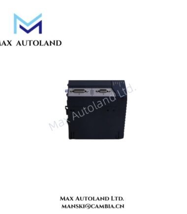
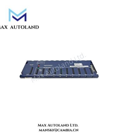
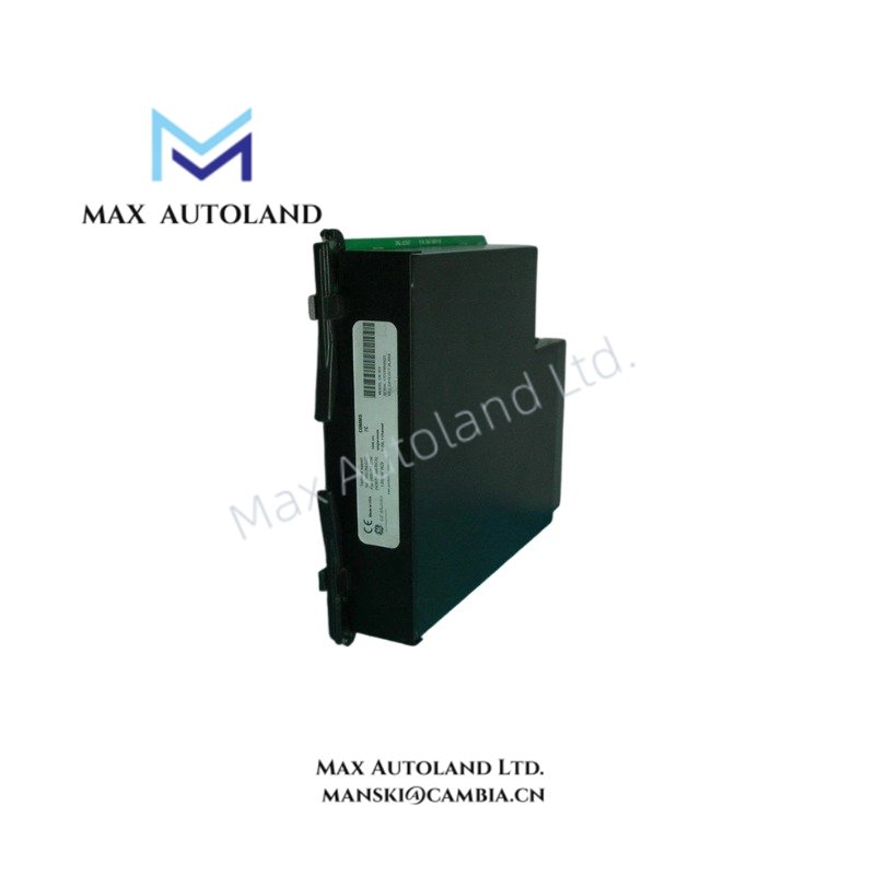
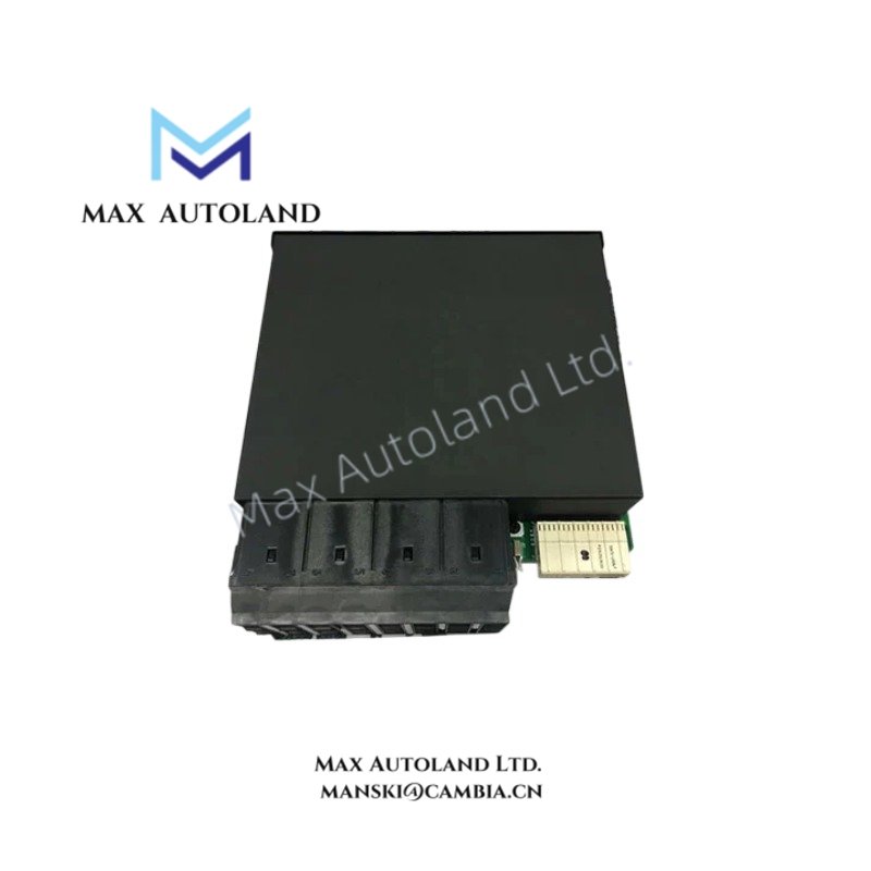
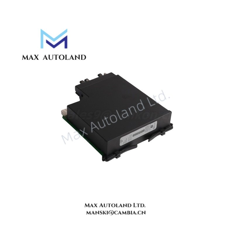
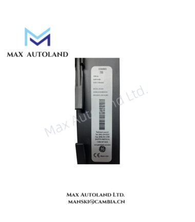
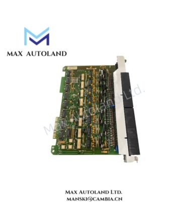
TheGE UR7CVserves as the primaryUR7CV I/O Moduleutilized to execute field signal acquisition and electrical interfacing across GE legacy control backplane architectures. The module implements discrete and analog signal termination, backplane data exchange, and galvanic separation between field wiring and controller-level processing domains.
Hardware Specifications
| Parameter | Specification |
|---|---|
| ModelBrand | GE UR7CV |
| Origin | United States (GE Industrial Systems lineage) |
| OperatingTemp | 0 degC to 60 degC |
| PowerConsumption | Low power backplane-fed module (exact value not specified) |
| Channel Configuration | Multi-channel discrete/analog interface (variant dependent) |
| Isolation Voltage | Up to 1500 VAC or equivalent DC isolation level (variant dependent) |
| Backplane Interface | GE proprietary rack/backplane communication bus |
| Mounting Type | Rack / backplane slot installation |
Industrial Control & Backplane Communication Characteristics
The UR7CV module operates within GE rack-based controller architectures where cyclic I/O data is exchanged through a deterministic backplane bus. Signal integrity is maintained through synchronized scan cycles between CPU and distributed I/O slots, with timing behavior constrained by legacy controller scan rates.
Firmware and hardware revision alignment is required for backplane compatibility, as mismatch conditions may result in I/O mapping failure or scan list desynchronization. The module supports deterministic cyclic updates typical of PLC-class execution environments, without external network abstraction layers.
Frequently Asked Questions
Q: Can the UR7CV module be hot-swapped during controller operation?
A: Hot-swap capability is system-dependent and constrained by rack controller design. Backplane power interruption during insertion may cause I/O state reset.
Q: Does the module require configuration after replacement?
A: Configuration is stored in controller memory or rack configuration data. Replacement modules must match hardware revision to ensure correct I/O mapping.
Q: What is the backplane current dependency?
A: The module draws operating power directly from the rack backplane. Current loading is determined by slot allocation and system power budget.
Field Installation Guidelines
Ensure controller rack power is fully isolated prior to insertion or removal of the module. Align module edge connectors precisely with backplane guides to prevent pin deformation. Maintain shielding continuity across adjacent modules where applicable. Field wiring should be routed with separation from high-voltage conductors to minimize electromagnetic coupling. All terminal connections must be torque-verified according to rack assembly specifications. Avoid mechanical stress on backplane connector during fastening.