
Overview
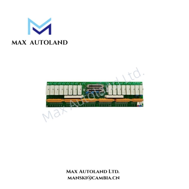
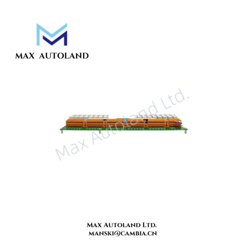
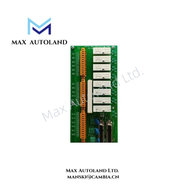
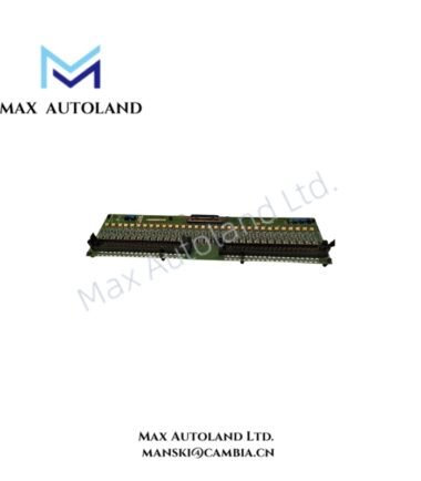
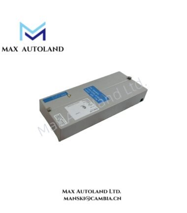
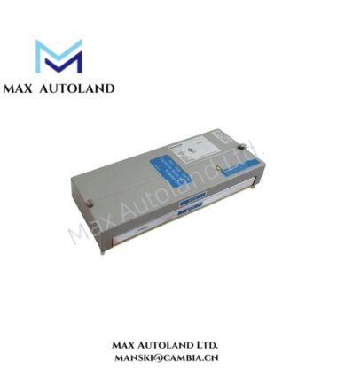
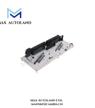
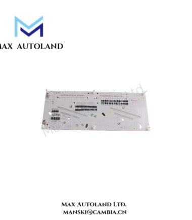
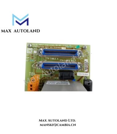
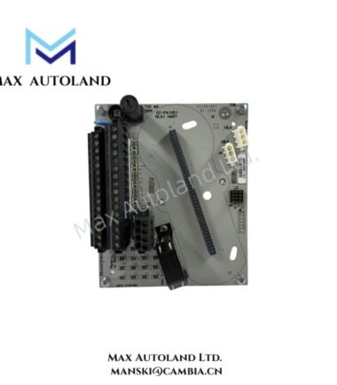
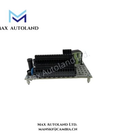
Configured for 24 VDC discrete signal acquisition, the Honeywell 51304441-100 (MU-TDID12 Digital Input Module) provides 32 input channels through a board assembly with two FTA ports. The supplied identification also marks this model as discontinued by the manufacturer.
Hardware Specifications
| Parameter | Specification |
|---|---|
| Model | 51304441-100 |
| Spare Model | MU-TDID12 |
| Brand | Honeywell |
| Module Type | Digital Input Module |
| Input Type | Discrete input |
| Number of Inputs | 32 |
| Input Voltage | 24 VDC |
| FTA Ports | 2 |
| Assembly Type | Board assembly |
| Dimensions | 46.2 x 12 x 5.3 cm estimated shipping size |
| Weight | 1.24 kg |
| Manufacturer Status | Discontinued by manufacturer |
Honeywell Digital Input Architecture
The MU-TDID12 uses 24 VDC discrete input channels to acquire binary field signals for a Honeywell control system. Each of its 32 input channels represents an on/off field condition rather than a continuous analog measurement.
Furthermore, the assembly provides two FTA ports for field termination connections. The supplied data does not specify channel-to-channel isolation, input threshold values, wetting current, diagnostic functions, or backplane power consumption; therefore, these parameters require confirmation from the applicable Honeywell documentation.
This module does not provide evidence of 4-20 mA HART, FOUNDATION Fieldbus, or Profibus PA functionality. Its stated electrical function is limited to 24 VDC, 32-channel discrete input acquisition.
Frequently Asked Questions
Q: What type of signals does the 51304441-100 accept?
A: The supplied specifications identify the module as a 32-input digital input board assembly operating with 24 VDC discrete signals.
Q: How many field termination connections are identified?
A: The supplied data specifies two FTA ports. It does not provide the individual channel allocation for each port.
Q: Is the 51304441-100 a current production module?
A: No. The supplied product identification states that the 51304441-100 is discontinued by the manufacturer.
Field Installation Guidelines
- Verify the module part number and MU-TDID12 designation before installation.
- Confirm the control system chassis and interface hardware support this specific board assembly.
- Isolate field power before connecting or removing field wiring.
- Confirm the 24 VDC field supply polarity before energizing the input circuits.
- Route discrete signal wiring separately from high-voltage and high-current conductors where practical.
- Maintain appropriate shielding and grounding practices according to the applicable Honeywell installation documentation.
- Secure the two FTA connections and inspect all terminals for proper mechanical engagement.
- Do not apply unspecified signal voltages to the input channels.
- Verify channel status after installation using the applicable system diagnostics and commissioning procedure.
- Because the supplied data does not define operating temperature, input thresholds, isolation ratings, or power consumption, obtain the applicable Honeywell technical documentation before final installation.


Reviews
There are no reviews yet.