

Overview
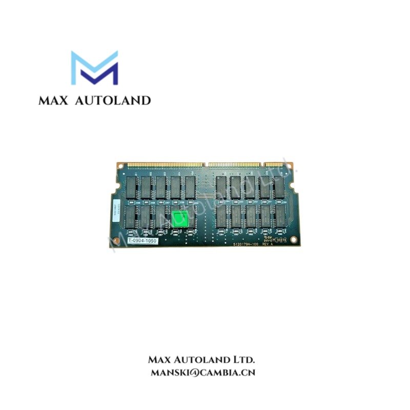
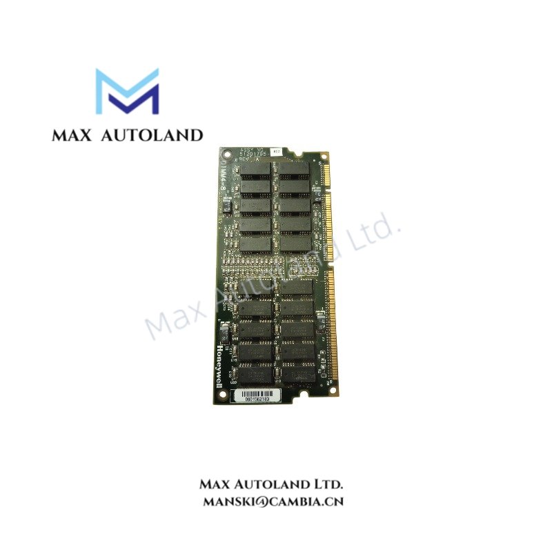
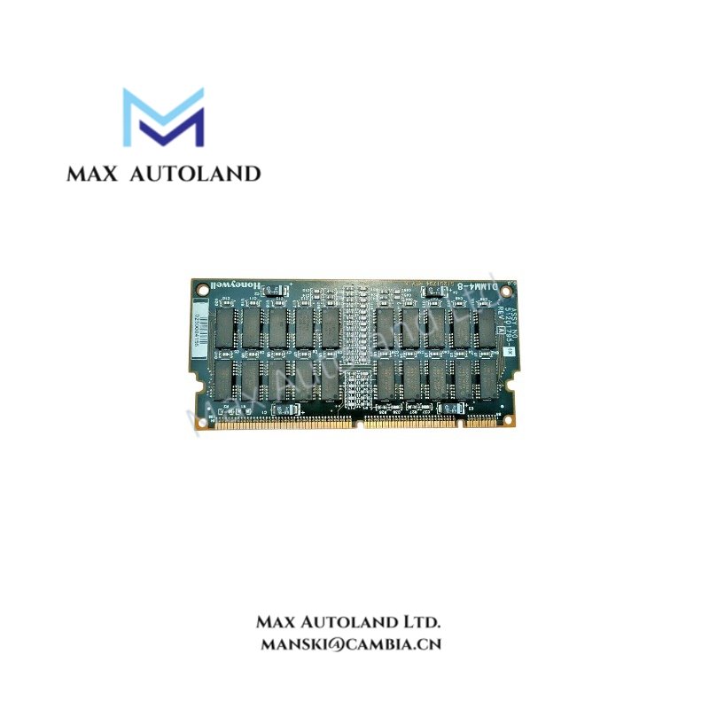
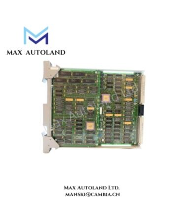
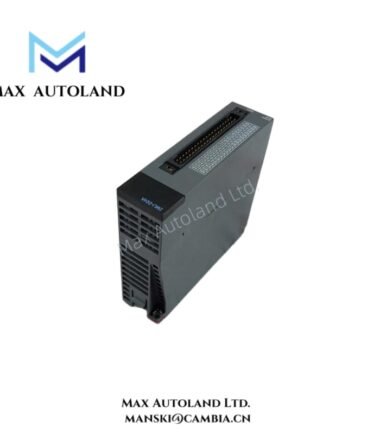
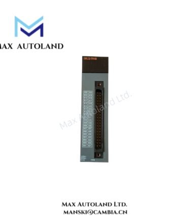
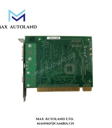
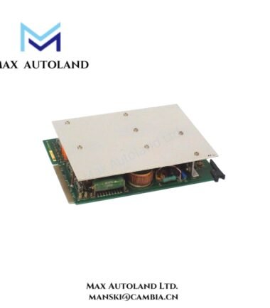
TheHoneywell 51201795-800,also cataloged as the51201795-800 Processor Memory Card / DIMM Board,serves as theprimary51201795-800 Processor Memory Card / DIMM Board utilized to execute processor-memory data handling across Honeywell Measurex distributed control system backplane platforms.
Suffix Breakdown & Model Matrix
No validated manufacturer-supplied suffix segmentation or variant encoding is defined for 51201795-800. The ordering code is treated as a single fixed hardware identifier mapped to a specific processor-memory assembly revision.
Hardware Specifications
| Parameter | Specification |
|---|---|
| ModelBrand | Honeywell 51201795-800 |
| Origin | USA / Honeywell Measurex legacy production |
| Weight | 0.15 kg to 0.6 kg (shipping dependent) |
| Dimensions | 14.00 cm x 1.00 cm x 7.00 cm (approx) |
| OperatingTemp | Not specified (system dependent) |
| PowerConsumption | Not specified (backplane supplied) |
| Processor Architecture | Motorola 68020 |
| Memory | 8 MB onboard DIMM RAM |
| Assembly Reference | 51201794-100 Base Board PWA |
Process Control Backplane Memory Execution Characteristics
Channel-to-Channel Data Handling and Fieldbus Interface Behavior
The Honeywell Measurex processor-memory architecture implements deterministic backplane communication with tightly coupled memory mapping between CPU execution space and I/O scan cycles. The Motorola 68020 core executes structured control logic while memory residency supports cyclic process image buffering. Channel-to-channel isolation is implemented at system architecture level through board segmentation and backplane partitioning, minimizing cross-domain memory corruption during scan execution. Integration is aligned with 4-20 mA loop data representation and legacy DCS register mapping conventions typical of Honeywell process control stacks.
Frequently Asked Questions
Q: Does the module support hot-swap insertion on live backplane systems?
A: No defined hot-swap specification is available. Insertion should be performed under system power-down conditions to avoid backplane bus contention and memory corruption.
Q: What is the backplane power dependency of the card?
A: Power is supplied directly from the host system backplane. Current draw and rail distribution are system design dependent and not specified at module level.
Q: Can firmware or onboard memory be upgraded in the field?
A: No field firmware upgrade interface is documented. Memory behavior is tied to hardware configuration and system-level controller image.
Field Installation Guidelines
Ensure system power is fully isolated before insertion or removal of the module. Verify backplane connector alignment prior to seating to prevent pin damage. Maintain electrostatic discharge protection using grounded handling procedures. Avoid mechanical stress on DIMM edge connectors during installation. Confirm system memory mapping recognition during initial power-up diagnostics through controller-level status registers. Do not apply uneven torque or leverage on the board during extraction.



Reviews
There are no reviews yet.