

Overview
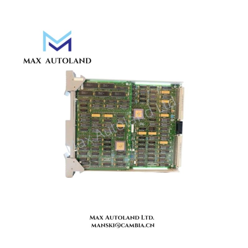
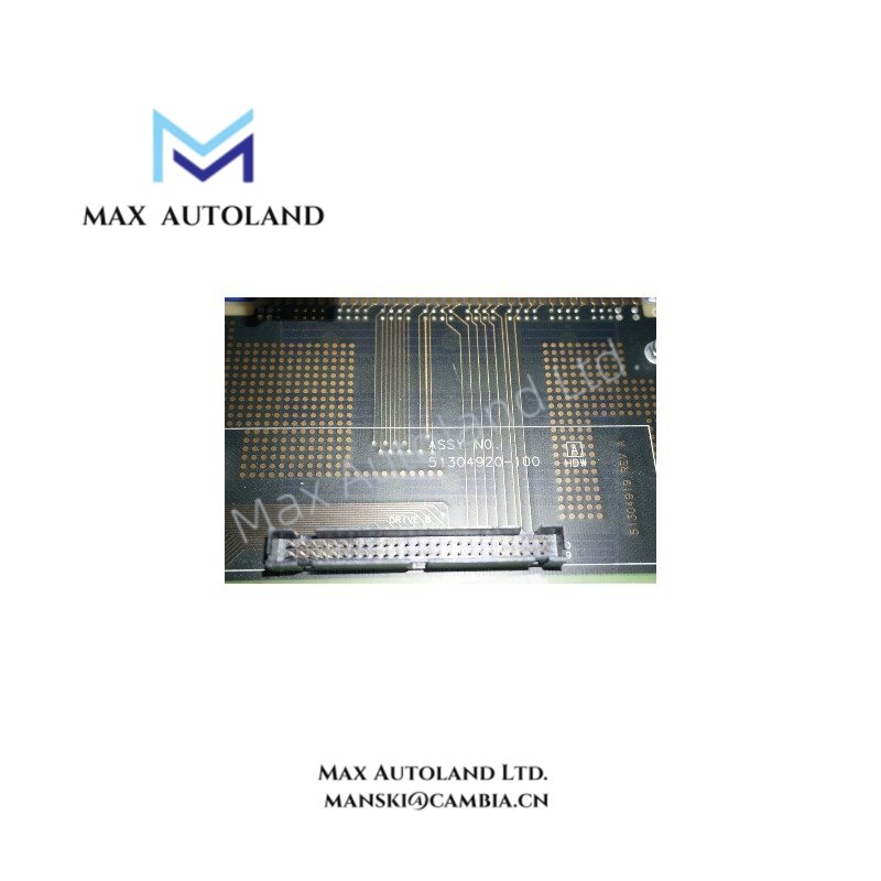
Configured for data interface signal routing in TDC3000 framework, the Honeywell 51304920-100 (51304920-100 Interface Board) provides direct physical/electrical execution within Honeywell TDC3000 process control backplane architecture. The module operates as a fixed-function interface board supporting low-level power distribution and TDC-specific communication pathways.
HardwareSpecifications
| Parameter | Specification |
|---|---|
| ModelBrand | Honeywell 51304920-100 |
| Origin | USA |
| Weight | 0.76 kg |
| Dimensions | 36.6 cm x 36.3 cm x 1.5 cm |
| OperatingTemp | 0 degC to 50 degC |
| StorageTemp | -20 degC to 70 degC |
| PowerConsumption | 5 VDC, approx. 1.5 W, 300 mA nominal |
| Function | TDC3000 Interface Board |
| Communication | TDC-specific protocol signaling |
| System Integration | TDC3000 framework backplane interface |
TDC3000 Backplane Interface and Signal Integrity
The module implements fixed routing for TDC3000 backplane communication channels, maintaining deterministic signal propagation between controller and subsystem nodes. Internal design supports protocol-level separation of TDC-specific data streams with stable electrical referencing at 5 VDC logic domain. Signal paths are optimized for low-noise transfer within cabinet-level installations, with board-level distribution aligned to Honeywell legacy DCS architecture constraints.
Frequently Asked Questions
Q: Does the 51304920-100 support hot-swap operation within the TDC3000 chassis?
A: No hot-swap capability is defined. Removal or insertion requires system power-down to avoid backplane signal disruption.
Q: What is the expected backplane electrical loading of the module?
A: The module operates at approximately 300 mA nominal current draw at 5 VDC, contributing to shared backplane power budgeting.
Q: Is firmware upgrade applicable to this interface board?
A: No field firmware layer is present; functionality is hardware-defined within TDC3000 architecture.
Field Installation Guidelines
Ensure chassis power is fully isolated before installation or removal. Align board edge connectors with TDC3000 backplane guides to prevent pin misalignment. Maintain controlled torque during mechanical securing to avoid PCB flex stress.
Use shielded cabinet grounding practices consistent with DCS enclosure standards. Keep signal routing separated from high-voltage or high-frequency conductors to minimize inductive coupling into backplane traces. Verify 5 VDC rail stability prior to system energization.





Reviews
There are no reviews yet.