
Overview
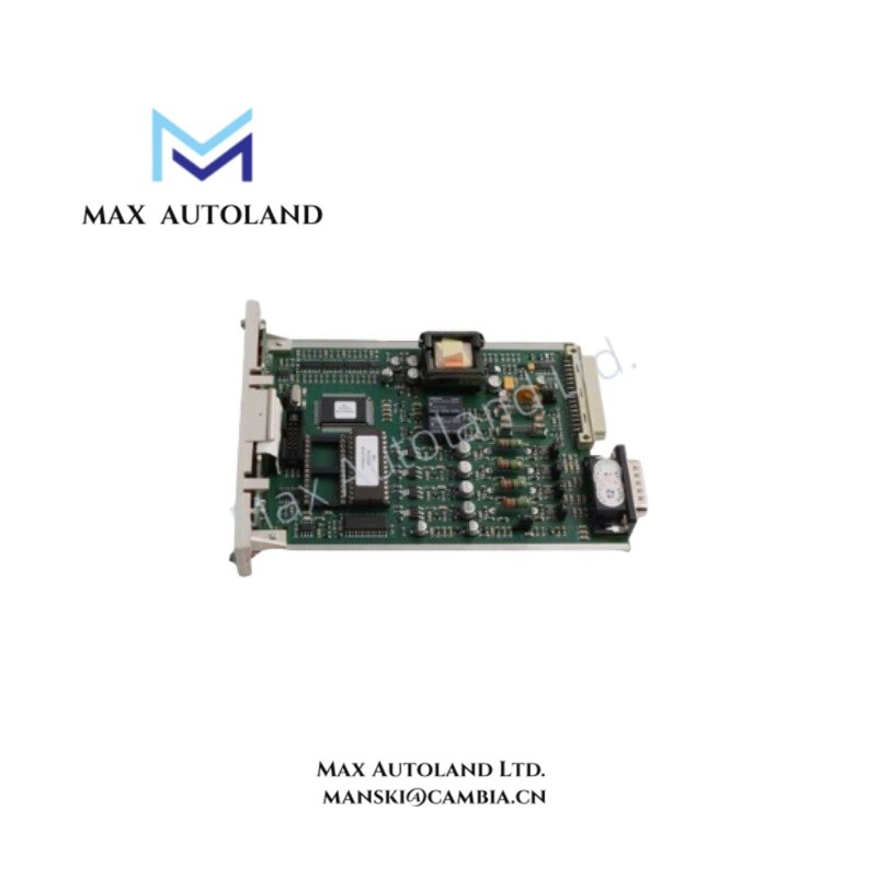
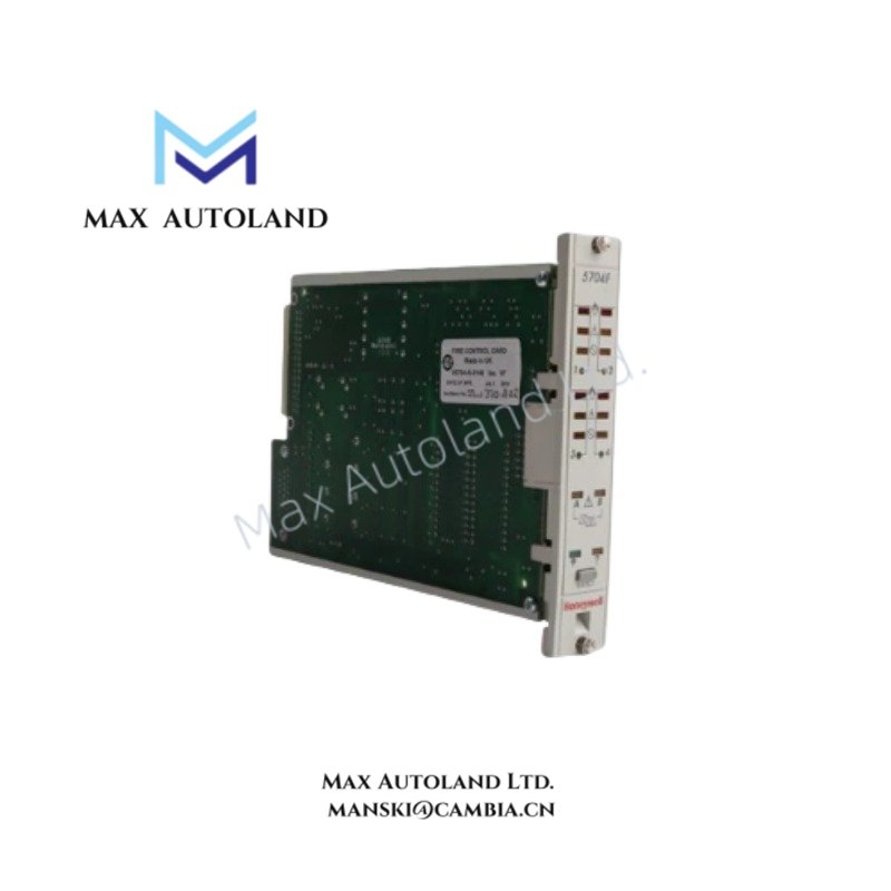
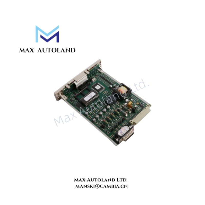
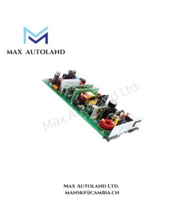
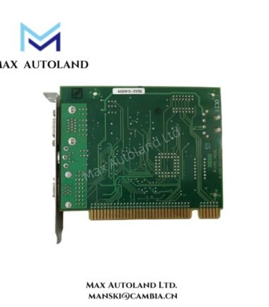
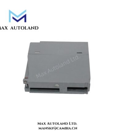
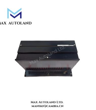
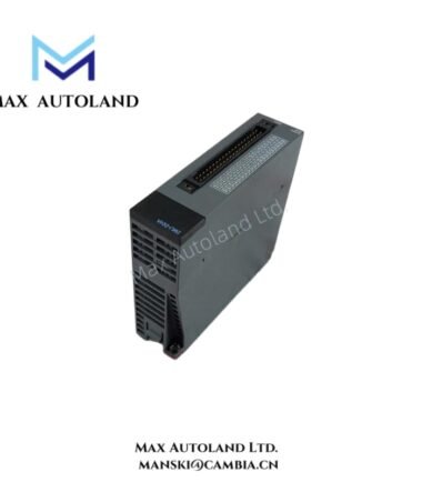
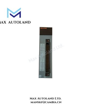
Configured for catalytic gas detector signal acquisition in System 57 rack architecture, the Honeywell 05704-A-0134 (05704-A-0134 control/interface module) provides direct physical/electrical execution of multi-channel input processing, alarm evaluation, and backplane communication within Honeywell System 57 gas detection platforms.
The module conditions low-level detector signals, executes threshold comparison logic, and routes status data through the System 57 backplane for centralized alarm and fault handling. All functional behavior is implemented through rack-level power distribution and microprocessor-based firmware stored in non-volatile memory.
HardwareSpecifications
| Parameter | Specification |
|---|---|
| Model | 05704-A-0134 |
| Brand | Honeywell |
| Origin | USA |
| Weight | 0.4 kg (reported) |
| Dimensions | 13.3 cm x 2.54 cm x 19.0 cm (reported) |
| OperatingTemp | -20 degC to +50/+70 degC (system dependent) |
| PowerConsumption | 24 VDC system rack supply (typical) |
| Channel Input Type | Catalytic gas detector inputs |
| Channel Count | 4 channels (reported configuration) |
| System Architecture | System 57 rack / backplane |
| Alarm Interface | LED status + relay outputs |
| Memory | Non-volatile EEPROM configuration storage |
Honeywell Process Control Signal Integration Characteristics
Within Honeywell System 57 instrumentation architecture, the module aligns with process control signal conditioning principles commonly used in DCS environments. Although optimized for gas detection inputs, its internal signal routing and alarm processing logic reflects standard industrial instrumentation behaviors such as 4-20 mA loop compatibility, HART-style field device integration concepts, and channel-to-channel signal separation strategies used to reduce cross-interference in multi-sensor racks.
Backplane communication operates as a deterministic rack bus, where each channel state is mapped into system-level alarm registers. In typical process instrumentation design patterns, similar modules may implement galvanic separation between input stages to maintain signal integrity under industrial noise conditions.
FrequentlyAskedQuestions
Q: Does the module support hot-swap operation within System 57 racks?
A: Hot-swap capability is dependent on the System 57 subrack backplane design. Electrical isolation of the slot must be verified before insertion or removal under live power conditions.
Q: What is the backplane communication behavior during fault conditions?
A: On internal fault detection, the module drives fault status bits onto the System 57 backplane and activates relay-based fault outputs if configured at system level.
Q: Can channel inputs operate independently in case of single-channel failure?
A: Each channel is processed independently at input stage, but shared power and backplane routing may propagate system-level fault indication depending on configuration logic.
FieldInstallationGuidelines
Ensure the module is installed only in a compatible Honeywell System 57 rack with verified backplane alignment. Maintain correct insertion force to avoid edge connector damage. Signal wiring from catalytic detectors must be routed using shielded cabling with single-point earth grounding at the control cabinet end to minimize ground loop formation.
Avoid routing detector signal lines parallel to high-voltage or VFD output conductors. Maintain minimum physical separation in accordance with industrial instrumentation wiring standards. Verify 24 VDC supply stability prior to module insertion to prevent transient backplane disturbance.





Reviews
There are no reviews yet.