
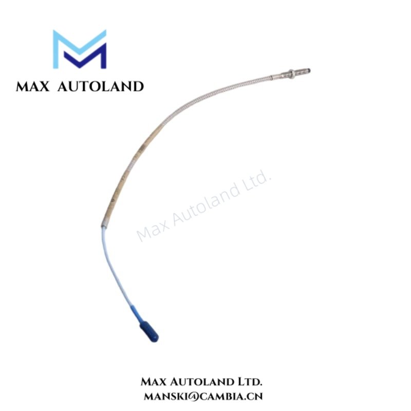
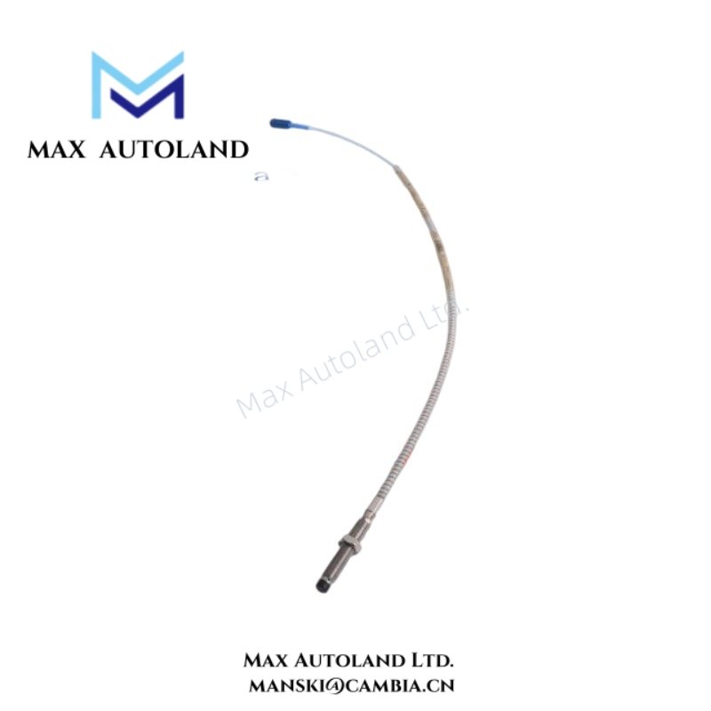
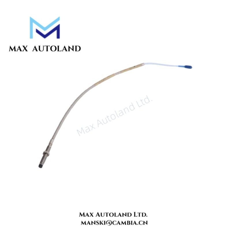

Overview
Suffix Breakdown & Model Matrix
No official structural decomposition is published for 330101-00-20-05-02-05 beyond manufacturer configuration coding. The suffix represents a factory-defined ordering key used to specify probe assembly configuration, including cable length, connector type, and installation variant.
Specifications
| ParameterSpecification | |
| Model | 330101-00-20-05-02-05 |
| Brand | Bently Nevada |
| Origin | Not specified |
| Weight | Not specified |
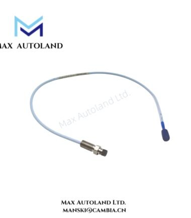
| Dimensions | 8 mm probe form factor |
| Operating Temp | Not specified |
| Power Consumption | Powered via Proximitor driver loop |
| Measurement Principle | Eddy-current displacement transduction |
| Output Signal | Analog voltage proportional to gap |
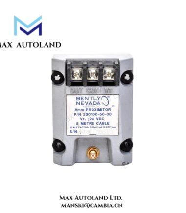
| System Series | 3300 XL 8 mm Proximity Transducer |
Eddy-Current Probe Scaling and Signal Stability (TSI Characteristics)
The probe operates by generating a high-frequency electromagnetic field at the probe tip. When the conductive shaft surface enters this field, the system induces eddy currents, and these currents actively modify coil impedance in real time. The Proximitor interface then converts this impedance variation into a calibrated voltage output.
In practice, scaling behavior follows factory calibration mapping, and this mapping translates physical gap displacement into a linearized voltage response. During commissioning activities, technicians validate gap response behavior against nominal bias conditions close to -10 VDC at defined mechanical clearance points.
In multi-channel installations, signal stability depends on controlled shielding geometry together with oscillator frequency consistency. This configuration reduces cross-talk between adjacent probe channels and preserves phase integrity, which supports rotor dynamic analysis across multiple measurement points.
Frequently Asked Questions (FAQ)
Q: Can the probe be disconnected under energized system conditions?
A: The probe remains passive in operation; however, if maintenance personnel disconnect it while the Proximitor loop is energized, the system may experience transient voltage disturbance and temporary signal loss until loop stabilization completes.
Q: Does cable configuration affect measurement accuracy?
A: Yes. Cable length and connector configuration directly influence impedance characteristics. Therefore, engineers must match calibration settings to the installed cable configuration to maintain correct displacement-to-voltage scaling.
Q: How does the system handle multiple probe inputs in one rack?
A: Each probe channel routes through an individual Proximitor driver path. The system then distributes load per channel, while overall capacity remains constrained by 3300 XL channel density and oscillator drive limits.
Field Installation Guidelines
Installers must mount the probe with a rigid mechanical reference relative to the monitored shaft surface. The probe face must align perpendicular to the rotor target so that the system maintains stable eddy-current field distribution.
Technicians should also maintain adequate spacing between adjacent probes to reduce electromagnetic coupling effects. Cable routing should follow shielded conduit paths, and installers should implement single-point shield grounding to prevent ground loop formation.
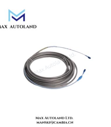
In addition, connector interfaces require controlled mechanical tightening to maintain stable electrical contact without introducing housing stress. Finally, installers must avoid excessive bending of extension cables, since impedance variation can degrade signal stability and measurement accuracy.





Reviews
There are no reviews yet.