

Overview
Specifications
| ParameterSpecification | |
| Model | 135322-01 |
| Brand | Bently Nevada |
| Origin | Baker Hughes / Bently Nevada |
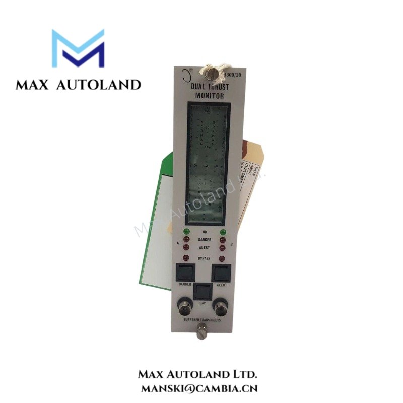
| Product Type | Dual Thrust Monitors |
| Measurement Technology | Eddy-current proximity transducer interface |
| Probe Compatibility | 3300 XL 8 mm Proximity Transducer System |
| Monitoring Function | Dual-channel thrust position monitoring |
| Signal Type | Probe-derived analog displacement signal |
| Operating Principle | Non-contact eddy-current sensing |
| Dimensions | Not specified in source data |
| Weight | Not specified in source data |
| Operating Temp | Refer to system environmental specifications |
| Power Consumption | Depends on installed monitor rack configuration |
Rotor Dynamics and Gap Voltage Validation
The 135322-01 monitor processes shaft axial position signals generated by the 3300 XL 8 mm transducer chain. Probe behavior follows calibrated eddy-current scaling between probe tip spacing and voltage output.
During commissioning, technicians commonly verify probe bias conditions near -10 VDC nominal gap targets. This validation confirms acceptable probe-to-target spacing before machinery startup.
The dual thrust monitoring arrangement supports comparative axial movement evaluation across rotating equipment assemblies. Signal separation practices reduce measurement ambiguity during transient rotor movement conditions.
Frequently Asked Questions
Q: Does the 135322-01 require matched probe system components?
A: Yes. The monitor operates within the 3300 XL transducer architecture and requires compatible probe, extension cable, and Proximitor sensor assemblies with calibrated system matching.
Q: Can probe gap voltage verification occur during installation?
A: Yes. Installers typically confirm static bias voltage before operational loading. Gap verification helps validate mechanical probe positioning and electrical loop integrity.
Q: Does the monitor require shielding and grounding controls for signal wiring?
A: Yes. Probe extension and monitor signal cabling should follow manufacturer grounding practices. Routing should avoid high-energy conductors and variable frequency drive output wiring.
Field Installation Guidelines
Install the monitor in the designated rack position defined by the associated 3300 monitoring system documentation.
Maintain probe cable separation from motor power conductors, relay coils, and switching power supplies. Use continuous shield integrity across the transducer loop.
Verify probe mounting rigidity before electrical calibration. Mechanical looseness can alter eddy-current scaling behavior and introduce false axial displacement readings.
During startup preparation, validate probe bias response against expected static shaft conditions. Deviations from nominal gap voltage behavior require mechanical alignment inspection or transducer loop troubleshooting.


Reviews
There are no reviews yet.