
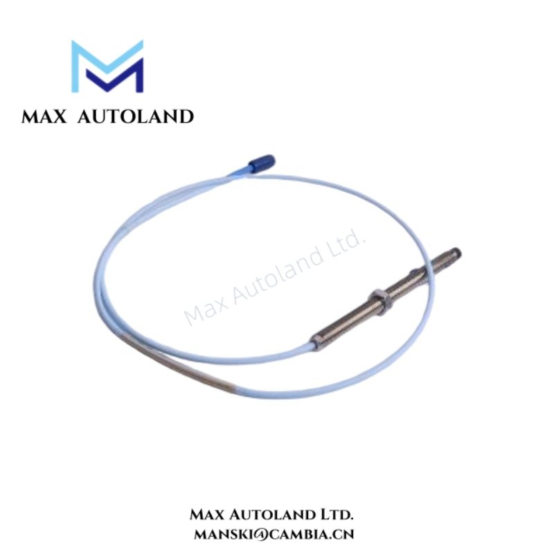
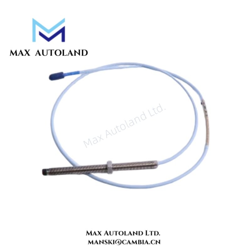
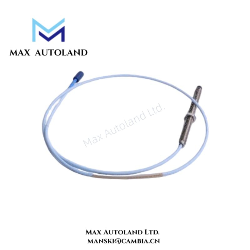
Overview
Suffix Breakdown & Model Matrix
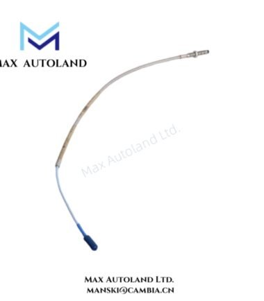
No published structural decoding is available for 330101-00-50-10-02-00 beyond factory configuration coding. The suffix functions as a manufacturer-defined identifier that encodes probe mechanical build options, cable length, connector termination, and installation variant selection.
Specifications
| ParameterSpecification | |
| Model | 330101-00-50-10-02-00 |
| Brand | Bently Nevada |
| Origin | Not specified |
| Weight | Not specified |
| Dimensions | 8 mm probe form factor |
| Operating Temp | Not specified |
| Power Consumption | Powered via Proximitor driver loop |
| Measurement Principle | Eddy-current displacement transduction |
| Signal Output | Analog voltage proportional to gap |
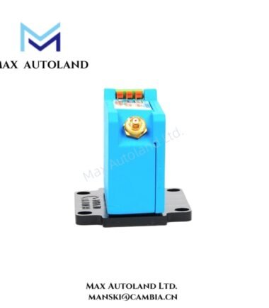
| System Compatibility | Bently Nevada 3300 XL series |
Eddy-Current Probe Scaling and Rotor Response Characteristics
The 3300 XL probe operates by generating a high-frequency electromagnetic field at the probe tip. When the conductive shaft enters this field, eddy currents form on the surface and alter coil impedance. The system converts this impedance variation into a calibrated voltage response through the Proximitor interface.
Scaling behavior follows factory-defined calibration curves that map physical gap displacement to linearized output voltage. During setup procedures, technicians reference gap voltage behavior against nominal bias points near -10 VDC under defined clearance conditions.
In multi-channel configurations, the probe maintains signal integrity through controlled shielding geometry. This reduces cross-channel coupling and preserves phase stability for rotor dynamic interpretation across adjacent measurement points.
Frequently Asked Questions (FAQ)
Q: Does the probe support direct hot-swap during energized operation?
A: The probe itself is passive; however, disconnecting it under energized Proximitor excitation may interrupt oscillator stability and generate transient measurement loss until the loop re-establishes equilibrium.
Q: How does the system handle multiple probe loading on a single rack?
A: Load distribution is managed at the Proximitor module level. Each channel contributes to oscillator drive consumption, and system limits are defined by 3300 XL channel density constraints.
Q: Does cable length affect measurement linearity?
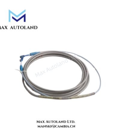
A: Yes. The probe-to-extension cable length alters impedance characteristics. Therefore, calibration must match installed cable configuration to maintain correct displacement-to-voltage scaling.
Field Installation Guidelines
Probe installation requires a rigid mechanical reference to the monitored rotor structure. The probe face must remain perpendicular to the shaft surface to preserve eddy-current field symmetry and stable linear response.
Installers should maintain minimum spacing between adjacent probes to reduce electromagnetic coupling effects. Cable routing must use shielded conduit paths, and the shield should terminate at a single grounding point to avoid ground loop formation.
Connector interfaces require controlled torque engagement to maintain stable electrical contact without inducing mechanical stress on the probe housing. Excessive bending of extension cables must be avoided, as impedance variation may affect signal stability.




Reviews
There are no reviews yet.