


Overview
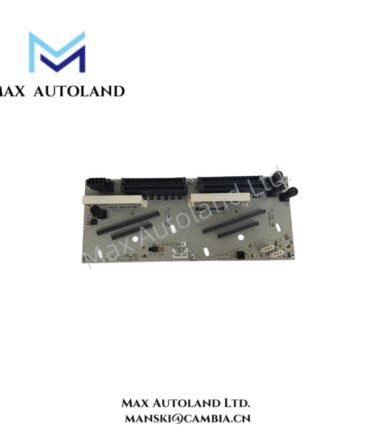
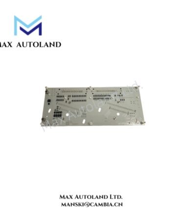
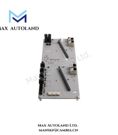
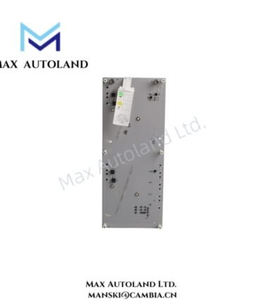
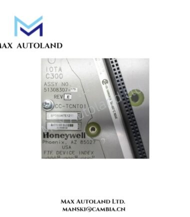
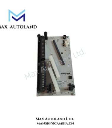
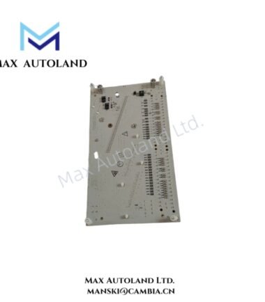
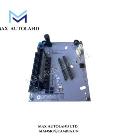
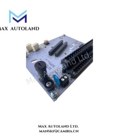
Configured for high-level analog signal termination in Honeywell TPS Distributed Control System architectures, the Honeywell MC-TAIH13 51309138-175 (MC-TAIH13 High-Level Analog Input Field Termination Assembly) provides direct electrical termination between field analog circuits and compatible Honeywell input processing hardware. The assembly supports analog voltage and current signal wiring and provides an organized cabinet interface for associated I/O processor connections.
Hardware Specifications
| Parameter | Specification |
|---|---|
| Model | MC-TAIH13 51309138-175 |
| Base Model | MC-TAIH13 |
| Brand | Honeywell |
| Product Type | High-Level Analog Input Field Termination Assembly (FTA) |
| Application Platform | Honeywell TotalPlant Solution (TPS) DCS |
| Input Type | High-level analog signals |
| Input Signal Range | 4-20 mA; 0-10 VDC; 0-20 VDC |
| Input Configuration | Multiple analog input points, depending on the associated I/O processor configuration |
| Associated I/O Hardware | Compatible with Honeywell IOP modules, including MU-PAIH03 / MC-PAIH03 where system configuration supports the interface |
| Isolation | Galvanic isolation specified between channels |
| Signal Function | Field signal termination and analog input interface |
| Mounting | Standard industrial modular cabinet mounting |
| Compliance | CE compliant, according to the provided data |
Process Signal Isolation and Analog Loop Interface
The MC-TAIH13 51309138-175 terminates field-side analog circuits before the signals enter the associated Honeywell input processing hardware. Consequently, correct termination practices directly affect signal stability and measurement quality.
The stated 4-20 mA interface supports standard process transmitter loops. In addition, the specified voltage input ranges allow connection to compatible analog voltage circuits. Channel-to-channel galvanic isolation reduces unwanted electrical interaction between connected circuits and helps limit ground-loop effects within multi-signal installations.
This Field Termination Assembly does not independently perform process control calculations. Instead, it provides the physical field wiring interface required by the associated analog input processing architecture. Therefore, signal scaling, channel configuration, and system-level diagnostics depend on the connected Honeywell I/O hardware and control-system configuration.
Frequently Asked Questions (FAQ)
Q: Can the MC-TAIH13 51309138-175 directly connect field transmitters to a Honeywell DCS cabinet?
A: The assembly provides the field-side termination interface for compatible high-level analog circuits. However, the complete connection arrangement must match the associated Honeywell IOP module and approved system wiring configuration.
Q: Does the MC-TAIH13 51309138-175 support both current and voltage signals?
A: The provided technical data specifies compatibility with 4-20 mA current loops and 0-10 VDC or 0-20 VDC voltage signals. The actual channel configuration must follow the associated I/O hardware documentation.
Q: Can the assembly be hot-swapped during operation?
A: The provided data does not specify hot-swap capability. Therefore, installation or removal should follow the applicable Honeywell cabinet maintenance procedure and site isolation requirements.
Field Installation Guidelines
- Verify the full model number MC-TAIH13 51309138-175 before installation.
- Confirm compatibility between the FTA, associated IOP hardware, and installed Honeywell TPS system configuration.
- Isolate cabinet power and field circuits when required by the approved maintenance procedure.
- Route analog signal wiring separately from high-power switching, motor, and variable-frequency drive conductors.
- Use shielded cable where the field wiring specification requires noise suppression.
- Apply cable shields according to the site grounding architecture and approved Honeywell wiring practice.
- Avoid connecting signal common conductors in a manner that defeats the specified channel isolation arrangement.
- Inspect terminal connections for conductor damage, loose terminations, and incorrect polarity before system energization.
- After commissioning, validate the measured input values through the connected I/O channel diagnostics and configured control-system engineering tools

Reviews
There are no reviews yet.