


Overview
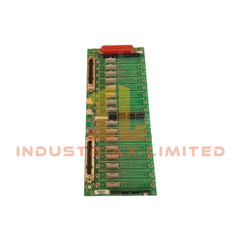
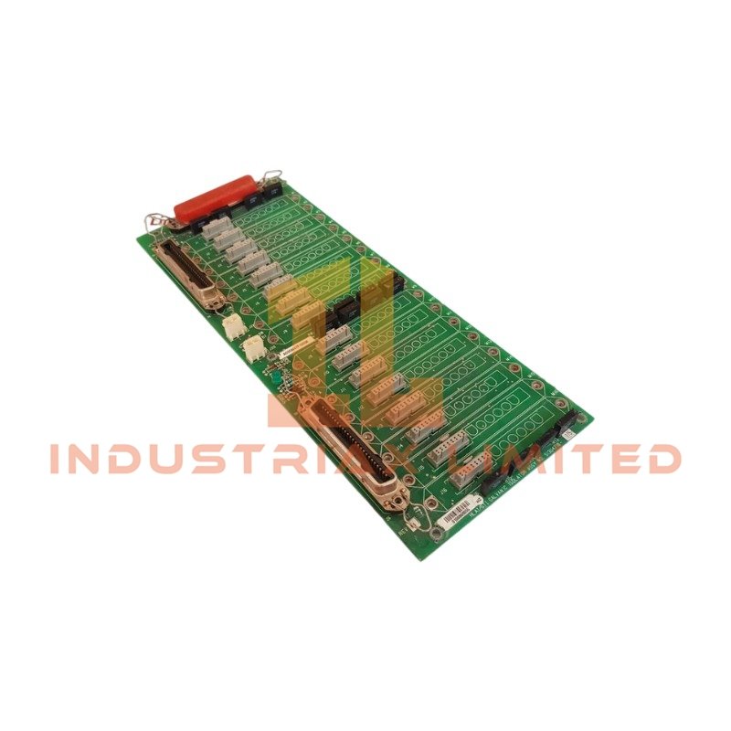
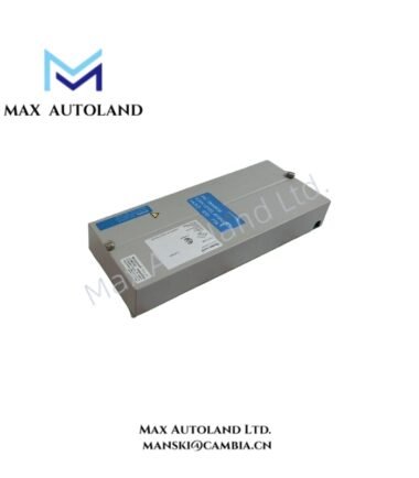
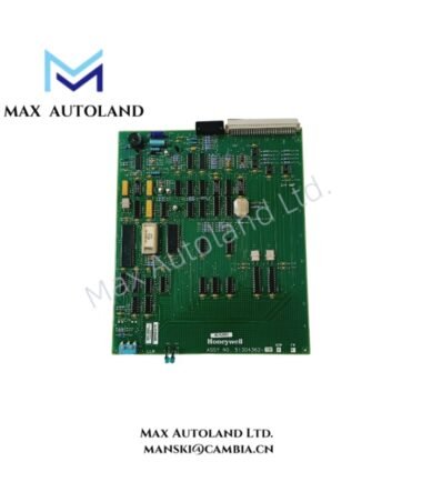
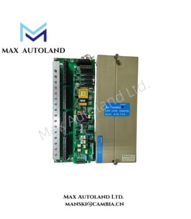
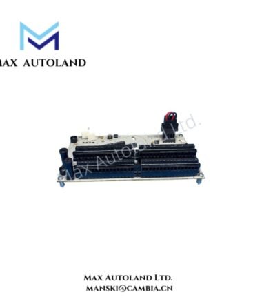
The Honeywell MC-GDID12 (51304640-575), also cataloged as the MC-GDID12 Digital Input FTA, interfaces 24 VDC field signals with Honeywell DCS input circuitry.
Hardware Specifications
| Parameter | Specification |
|---|---|
| Model | MC-GDID12 |
| Part Number | 51304640-575 |
| Brand | Honeywell |
| Product Type | Digital Input Field Termination Assembly |
| Input Channels | 16 Digital Inputs |
| Nominal Input Voltage | 24 VDC |
| Input Signal Range | 0 to 30 VDC |
| Isolation | Galvanic Isolation / GI/IS interface |
| System Compatibility | Honeywell TDC 3000, Experion PKS |
| Mounting | DIN rail or panel mounting |
| Operating Temp | 0 deg C to 60 deg C |
| Storage Temp | -40 deg C to 85 deg C |
| Relative Humidity | 5% to 95%, non-condensing |
DCS Digital Signal Isolation and Termination
The MC-GDID12 accepts discrete field signals within the stated 0 to 30 VDC range. Its 16-channel configuration provides individual digital input termination for field wiring connected to compatible Honeywell control-system infrastructure.
Galvanic isolation separates field-side electrical circuits from the associated control interface. Therefore, the installation can reduce the effects of ground-potential differences and unwanted electrical coupling between connected circuits.
For DCS integration, verify the specific FTA termination scheme and associated Honeywell I/O hardware before wiring. The supplied data identifies compatibility with TDC 3000 and Experion PKS platforms but does not define a specific controller-side interface pinout.
Frequently Asked Questions
Q: How many digital input channels does the MC-GDID12 provide?
A: The supplied specification identifies 16 digital input channels.
Q: What field voltage range does the MC-GDID12 accept?
A: The stated input signal range is 0 to 30 VDC, with 24 VDC specified as nominal input voltage.
Q: Does the supplied data confirm hot-swap operation?
A: No. The supplied documentation does not specify hot-swap capability. Follow the applicable Honeywell installation procedure before removing or installing the assembly.
Field Installation Guidelines
- Confirm the MC-GDID12 part number and terminal assignment against the project wiring documentation before installation.
- Isolate field power before terminating or modifying digital input wiring.
- Route digital signal wiring separately from high-voltage power conductors where practical.
- Use the designated protective-earth and signal-ground arrangement specified by the system installation documentation.
- Avoid creating unintended ground loops through cable shields or auxiliary grounding connections.
- Verify field polarity and signal voltage before connecting each digital input channel.
- Inspect terminal tightness and conductor condition before commissioning.
- After wiring, perform point-to-point checks and confirm the expected digital state at the DCS interface.





Reviews
There are no reviews yet.