
Overview
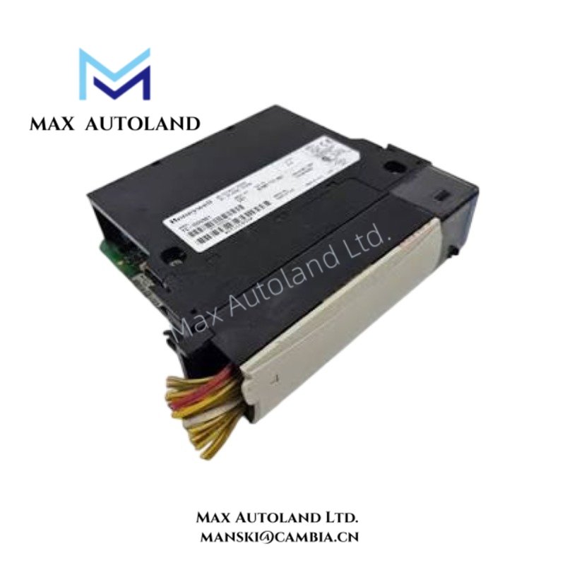
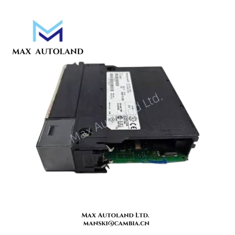
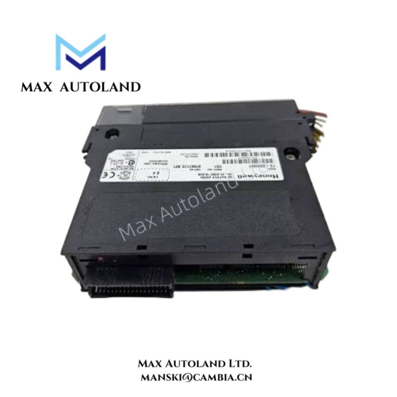
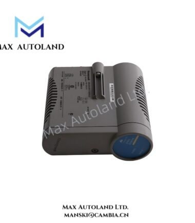
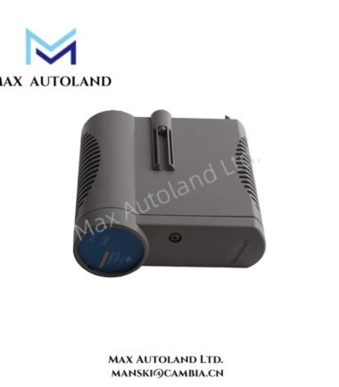
Configured for fail-safe analog signal generation in Honeywell safety control systems, the Honeywell FC-SAO-0220M (SAO-0220M Fail-Safe Analog Output Module) provides two isolated current outputs. Each channel supports 0-20 mA or 4-20 mA operation in active or passive mode, while independent monitoring supports output de-energization.
Hardware Specifications
| Parameter | Specification |
|---|---|
| Model | FC-SAO-0220M |
| Base Model | SAO-0220M |
| Brand | Honeywell |
| Product Type | Fail-Safe Analog Output Module |
| Number of Channels | 2 |
| Output Type | 0-20 mA or 4-20 mA, active or passive |
| Channel Isolation | Galvanically isolated from supply voltage |
| D/A Converter Resolution | 12-bit |
| Off Current | < 0.05 mA |
| Loop Powering | Maximum loop resistance: 600 Ohm; maximum output voltage: 30 VDC |
| External Powering | Maximum 40 VDC; minimum voltage drop <= 7.5 V |
| Load Type | Resistive or capacitive loads; inductive loads not supported |
| 5 VDC Consumption | 30 mA |
| 24 VDC Consumption | 65 mA + 30 mA per active output |
| WDG Input Current | 0.5 mA |
| Diagnostics | Output value accuracy tests, de-energization capability, and cross-talk monitoring |
| Safety Architecture | Independent processor and watchdog can separately de-energize outputs |
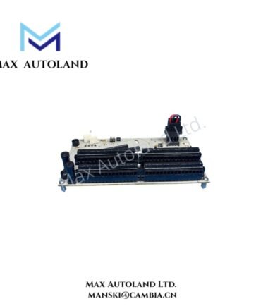
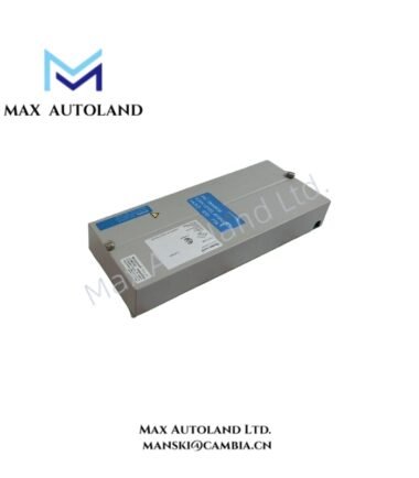
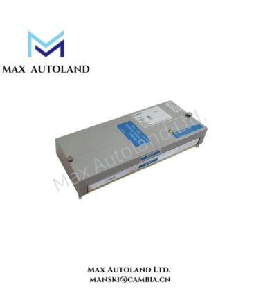
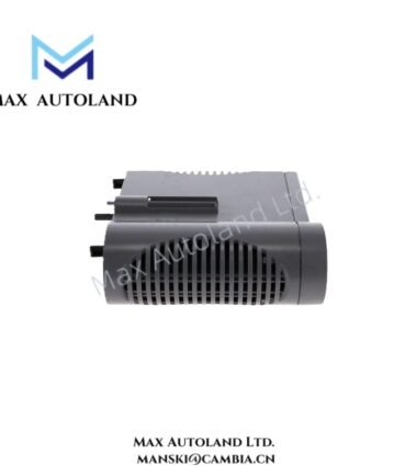
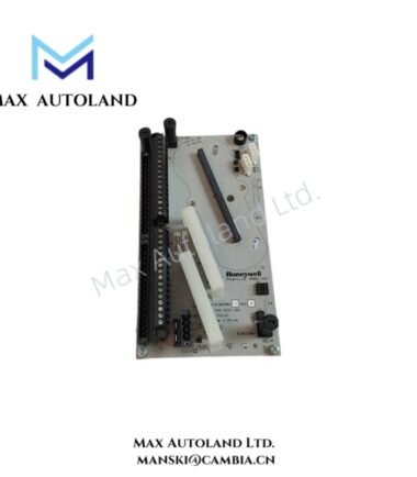
| Form Factor | Rack-mounted plug-in module |
| Module Size | 4 TE, 3 HE / 4 HP, 3U |
| Key Coding | Module code: holes A9, C5; chassis code: large pins A9, C5 |
| Approvals / Compliance | CE, TUV, UL, CSA, FM |
Fail-Safe Analog Output Architecture
The FC-SAO-0220M converts controller output data into two current-loop signals. The 12-bit D/A converter provides the specified analog output resolution.
Each output supports either 0-20 mA or 4-20 mA operation. The module also supports active and passive output configurations. For loop-powered operation, the specified maximum loop resistance is 600 Ohm, with a maximum output voltage of 30 VDC.
The module supports resistive and capacitive loads. However, the provided specifications do not support inductive loads.
Diagnostic and De-Energization Functions
The module monitors output value accuracy and cross-talk between channels. It also provides de-energization capability for the analog outputs.
An independent processor and watchdog provide separate output de-energization paths. Therefore, the output architecture does not depend solely on the normal processing path to place the output in its de-energized condition.
The WDG input current is specified as 0.5 mA. The module also monitors its 5 VDC and 24 VDC supply requirements through the specified power consumption values.
Frequently Asked Questions
Q: How many analog outputs does the FC-SAO-0220M provide?
A: The module provides two analog output channels. Each channel supports 0-20 mA or 4-20 mA operation.
Q: Can the FC-SAO-0220M drive inductive loads?
A: No. The specified load types are resistive and capacitive. Inductive loads are not supported.
Q: What physical installation format does the module use?
A: The FC-SAO-0220M uses a rack-mounted plug-in format with a specified size of 4 TE, 3 HE / 4 HP, 3U. Key coding uses holes A9 and C5 on the module and large pins A9 and C5 on the chassis.
Field Installation Guidelines
Install the module in the designated rack position and verify that the module and chassis key coding match before insertion.
Confirm the field wiring configuration before applying power. The output circuit must match the selected active or passive operating arrangement.
Keep analog signal wiring separated from high-current switching conductors and other sources of electrical interference. Use appropriate shield termination according to the control-system installation design.
Verify loop resistance before commissioning a loop-powered output. Keep the total loop resistance within the specified 600 Ohm maximum.
Do not connect inductive loads to the module outputs. Check the external supply voltage and output voltage-drop requirements before energizing externally powered circuits.
Before operation, verify the 5 VDC and 24 VDC supply requirements and confirm that each output remains within its configured current range. Then perform the available output accuracy and diagnostic checks.

Reviews
There are no reviews yet.