
Overview
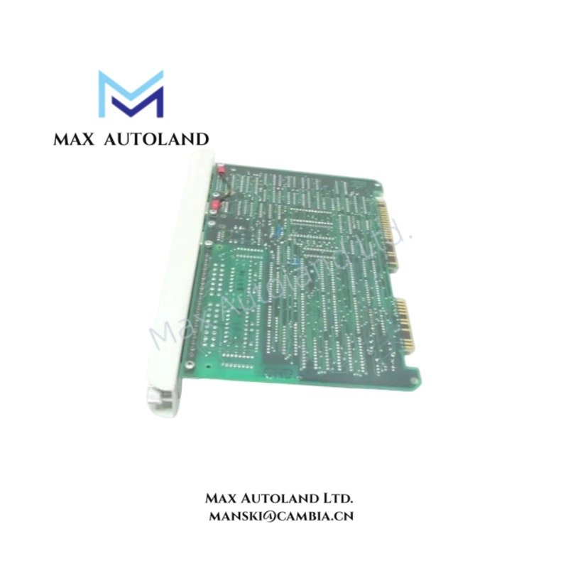
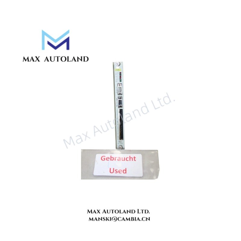
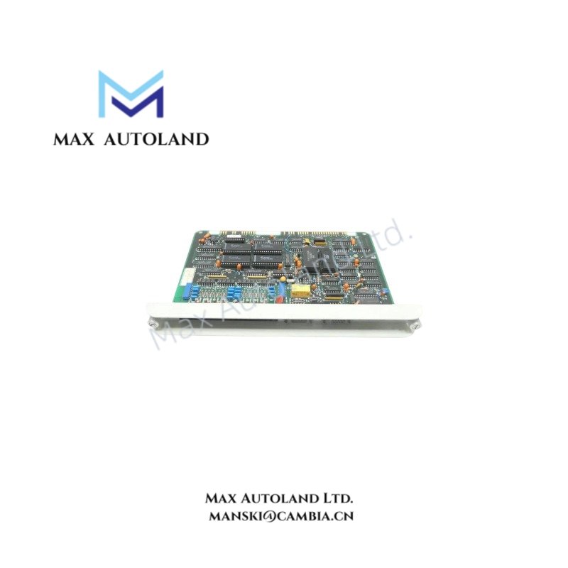
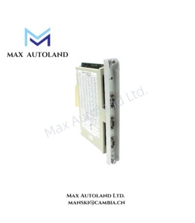
Configured for incremental encoder signal acquisition and axis-level servo feedback processing in Honeywell ISSC 600 System,the Honeywell 622-1030 (622-1030 Servo Axis Module) provides direct physical/electrical execution for closed-loop motion data handling. The module interfaces with incremental encoder inputs to generate position and velocity feedback signals for downstream control processing within the servo axis architecture. Signal conditioning and backplane communication are executed at board level without embedded motion control logic.
Suffix Breakdown & Model Matrix
Single fixed-order designation 622-1030 is used. No documented suffix segmentation or functional sub-variant encoding is defined for this module. Configuration is determined at system integration level within the ISSC 600 hardware frame.
Hardware Specifications
| Parameter | Specification |
|---|---|
| ModelBrand | Honeywell 622-1030 |
| Origin | Manufacturer: Honeywell / ISSC |
| Weight | 0.6 kg |
| Dimensions | 3.0 cm x 26.7 cm x 17.3 cm |
| OperatingTemp | Not specified (system dependent enclosure rating) |
| PowerConsumption | Not specified |
| Core Function | Servo axis signal interface for incremental encoder feedback |
| System Compatibility | Honeywell ISSC 600 System |
Honeywell Process Control Signal Interface Characteristics
FOUNDATION Fieldbus and 4-20 mA Signal Conditioning Layer
The module architecture aligns with Honeywell distributed control system signal handling conventions, supporting integration of analog feedback pathways commonly standardized as 4-20 mA process loops. Within ISSC 600 system topology, encoder-derived pulse trains are translated into deterministic position feedback streams for backplane processing. Channel-level electrical separation principles are applied at interface stages to minimize cross-domain signal interference in dense rack configurations.
Frequently Asked Questions
Q: Does the 622-1030 process raw incremental encoder signals directly?
A: The module accepts incremental encoder pulse inputs and performs hardware-level conditioning prior to backplane transmission. No standalone motion computation is embedded.
Q: Is hot-swap supported on the ISSC 600 backplane for this module?
A: Hot-swap behavior is system-frame dependent. Electrical removal under load requires adherence to rack-level backplane isolation sequencing.
Q: Does the module implement galvanic isolation between encoder input and system bus?
A: Isolation is implemented at interface stage consistent with industrial DCS signal separation practices, but isolation rating is defined by system backplane design.
Field Installation Guidelines
- Ensure backplane is fully de-energized prior to module insertion or removal unless rack is explicitly rated for live maintenance.
- Verify incremental encoder shielding is terminated at single-point earth ground to reduce high-frequency noise coupling.
- Maintain separation between encoder cabling and high-voltage switching conductors inside cabinet routing channels.
- Confirm module seating alignment on ISSC 600 backplane connector before applying mechanical locking force.
- Avoid bending stress on rear connector pins during installation or extraction operations.






Reviews
There are no reviews yet.