
Overview
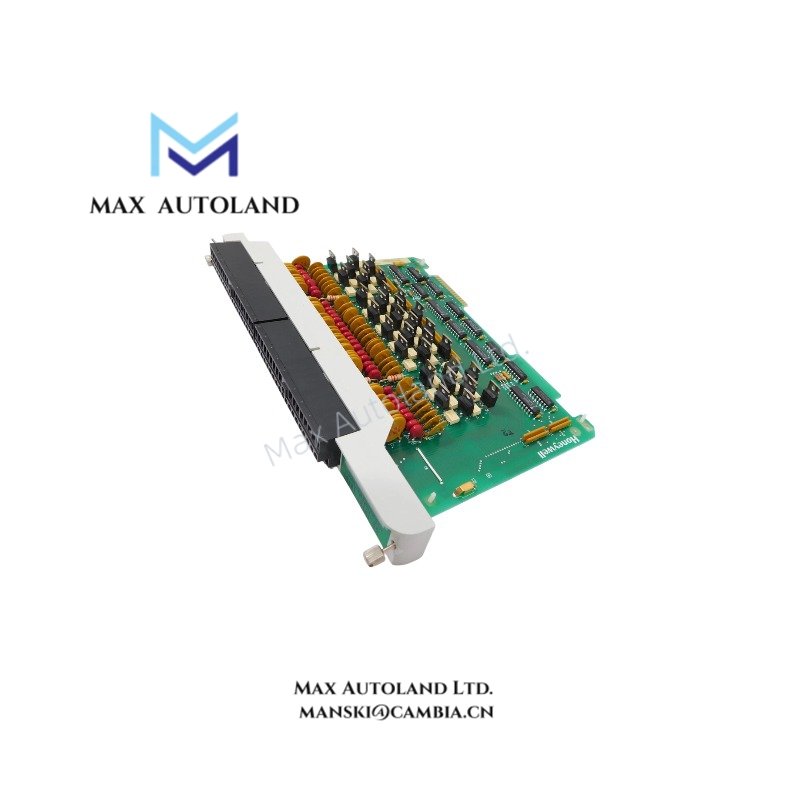
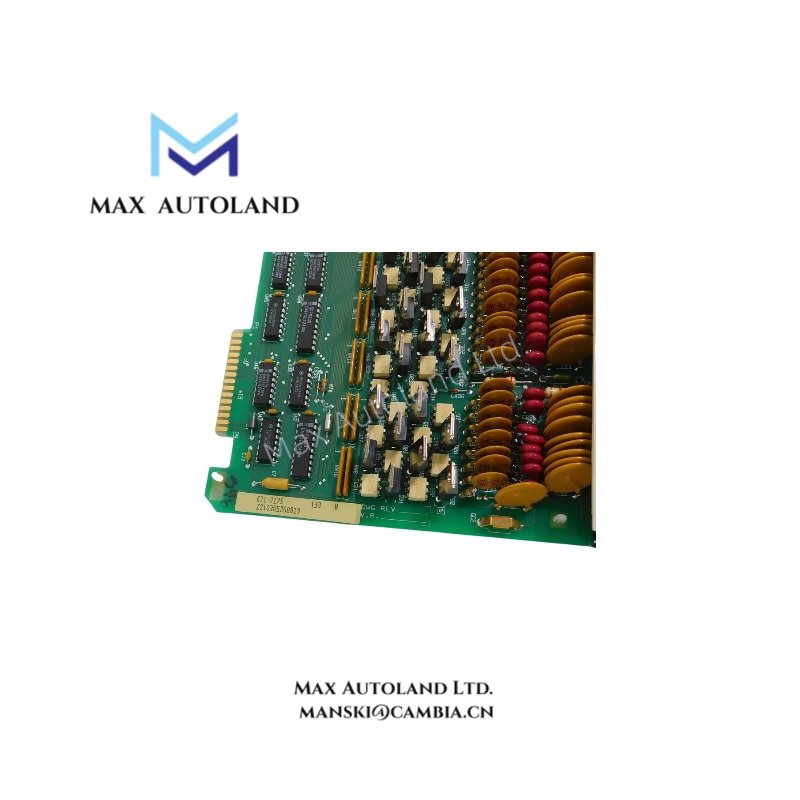
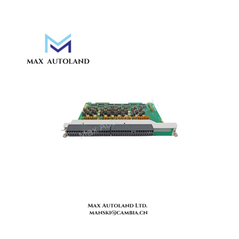
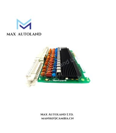
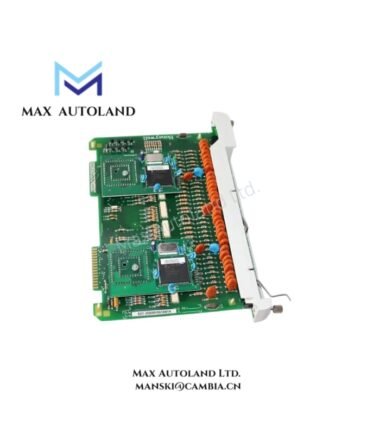
The Honeywell 621-2175R, also cataloged as the 621-2175 Isolated Analog Input Module, operates as a dedicated hardware component for high-integrity analog signal acquisition and digitization within the Honeywell IPC 620 programmable controller system.
Suffix Breakdown & Model Matrix
| Suffix | Description |
|---|---|
| R | Ruggedized or revised version with enhanced electrical and mechanical specifications |
Hardware Specifications
| Parameter | Specification |
|---|---|
| Model | 621-2175R |
| Brand | Honeywell |
| Origin | USA |
| Weight | Not specified (refer to IPC 620 rack installation manual) |
| Dimensions | Standard IPC 620 single-width I/O module form factor |
| Operating Temp | 0 deg C to 60 deg C |
| Storage Temp | -40 deg C to 85 deg C |
| Relative Humidity | 5 % to 95 % non-condensing |
| Power Consumption | 5 VDC at 350 mA typical |
| Channels | 8 differential isolated inputs |
| Input Signal Types | 4-20 mA, 0-20 mA; 1-5 VDC, 0-10 VDC (jumper/software selectable) |
| Input Impedance | Voltage mode: ≥ 1 MΩ; Current mode: 250 Ω internal precision resistor |
| Resolution | 12-bit ADC |
| Accuracy | ± 0.1 % of full scale at 25 deg C |
| Temperature Coefficient | ± 0.005 % of full scale per deg C |
| Update Time | < 25 ms for all 8 channels |
| Common Mode Rejection | > 80 dB at 60 Hz |
| Isolation Voltage | Channel-to-channel ≥ 1000 V RMS; Channel-to-logic ≥ 1500 V RMS |
Channel-to-Channel Isolation and Noise Immunity
The module employs channel-to-channel and channel-to-logic galvanic isolation to suppress ground loop currents and cross-talk between sensors. This isolation scheme supports accurate measurement in electrically noisy environments by preventing transient overvoltages from propagating across channels or into the backplane logic circuits.
Frequently Asked Questions
Q: Can the 621-2175R be replaced without powering down the IPC 620 rack?
A: Yes. The module supports hot-swap replacement; however, proper electrostatic discharge precautions must be observed during handling.
Q: How is input type configuration performed?
A: Input ranges are selected via onboard jumpers or software configuration within the IPC 620 control program.
Q: What diagnostic indicators are present on the module?
A: Onboard LEDs indicate power status, operational state, and per-channel fault conditions such as open-loop or out-of-range signals.
Field Installation Guidelines
Mount the module in an IPC 620 rack slot designated for analog input modules. Ensure proper seating until the module locking mechanism engages fully. Route shielded twisted-pair wiring to each differential input, grounding the shield drain wire at the rack ground bus only. Verify jumper settings before energizing the system. Avoid routing analog input cables parallel to high-power AC lines to minimize electromagnetic interference.




Reviews
There are no reviews yet.