



Overview
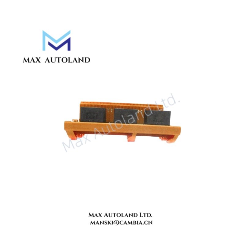
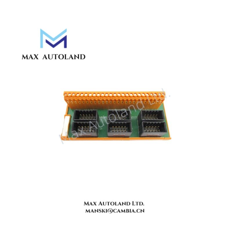
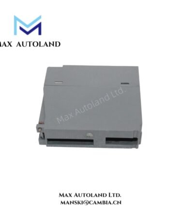
The Honeywell FTA-T-02, also cataloged as the FTA-T-02 Fail-safe Digital Output FTA, operates as a dedicated hardware component for fail-safe digital output signal termination within Honeywell safety and process control systems. It provides physical field termination for 24 output channels arranged in isolated wiring groups.
Suffix Breakdown & Model Matrix
The available documentation identifies FTA-T-02 as a fixed catalog model. No official suffix or ordering matrix is specified; therefore, no suffix interpretation is provided.
Hardware Specifications
| Parameter | Specification |
|---|---|
| Model | FTA-T-02 |
| Brand | Honeywell |
| Product Type | Fail-safe Digital Output FTA |
| Approvals | CE, UL |
| Number of Channels | 24 (6 groups of 4 channels) |
| Supported Output Voltage | 24 VDC, 48 VDC, 60 VDC |
| Maximum Voltage | 36 VAC / 50 VDC (IEC 1010 Overvoltage Category III); 125 VAC / 150 VDC (IEC 1010 Overvoltage Category II) |
| Maximum Continuous Current per Channel | 2 A |
| Terminal Type | Screw terminals |
| Maximum Wire Size | 0.25 cm2 (AWG 14) |
| Wire Strip Length | 0.7 cm |
| Terminal Tightening Torque | 0.5 Nm |
| Mounting | DIN EN TS32 or TS35 x 7.5 rail |
| Rail Length Required | 14.6 cm |
| Dimensions | 14.5 cm x 7 cm x 5.7 cm |
Channel Isolation Considerations
The FTA-T-02 is designed as a field termination assembly for fail-safe digital outputs. The documentation specifies six groups of four output channels, simplifying field wiring organization and maintenance. Isolation values between channels are not stated in the available technical data. System grounding, cable routing, and shield termination should therefore follow Honeywell installation practices to minimize electrical interference between adjacent field circuits.
Frequently Asked Questions
Q: Does the FTA-T-02 support hot replacement while field wiring remains energized?
A: The available documentation does not specify hot-swap capability. Module replacement procedures should follow the controller and system maintenance instructions before disconnecting field wiring.
Q: What is the maximum continuous load for each output channel?
A: Each channel supports a maximum continuous current of 2 A within the specified electrical ratings.
Q: Which conductor size is supported by the screw terminals?
A: The termination accepts conductors up to 0.25 cm2 (AWG 14). The specified strip length is 0.7 cm, and the recommended terminal tightening torque is 0.5 Nm.
Field Installation Guidelines
- Verify that supply voltage matches the supported field output configuration before wiring.
- Mount the assembly on a DIN EN TS32 or TS35 x 7.5 rail with at least 14.6 cm of available rail length.
- Observe the specified wire strip length and terminal tightening torque to maintain secure electrical connections.
- Separate output wiring from high-energy power cables to reduce conducted electrical noise.
- Terminate cable shields according to the system grounding practice to minimize unwanted coupling.
- Confirm channel grouping before commissioning because the assembly is organized into six groups of four output channels.




Reviews
There are no reviews yet.