
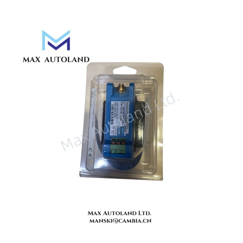
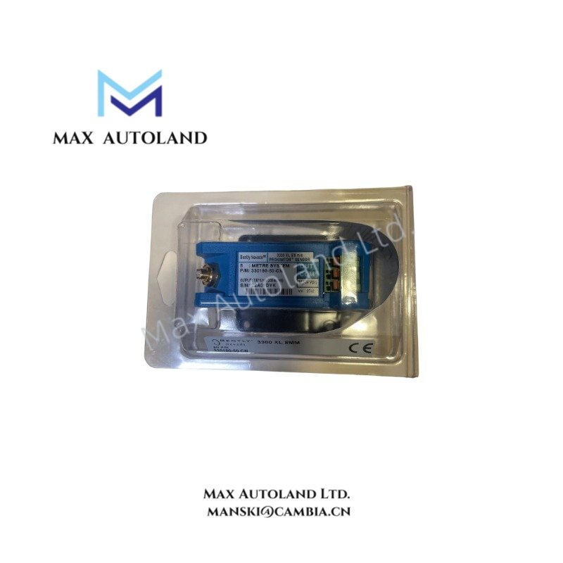
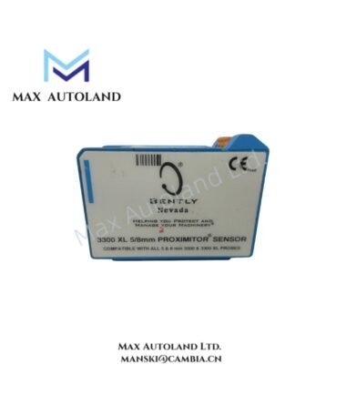
Overview
Hardware Specifications
| Parameter | Specification |
|---|---|
| Brand | Bently Nevada |
| Model | 330180-50-CN |
| Origin | USA |
| Weight | 0.22 kg |
| Dimensions | 8 x 6 x 6.5 cm |
| Operating Temp | -40 degC to +85 degC |
| Power Consumption | External via monitor (-24 VDC nominal) |
| Channels | Single channel per module |
| Frequency Response | 0.5 Hz to 12 kHz (+/- 3 dB) |
| Scale Factor | 200 mV/mil (7.87 V/mm) |
| System Length | 5.0 meters (16.4 feet) |
| Mounting Option | Panel mount |
| Agency Approval | CN (Country-specific approvals) |
| LED Indicators | Power (Green) |
| Terminals | Screw terminals (2.5 mm2) |
| Tariff Code | 8537101190 |
Eddy-Current Probe Scaling and Gap Voltage Validation
The hardware executes precise eddy-current probe scaling to generate a continuous voltage output directly proportional to the static and dynamic distance between the probe tip and the observed target. During installation and calibration, gap voltage validation targets a nominal -10 VDC baseline, representing the midpoint of the linear operating range. This calibration ensures stable scale factor performance across the standard 200 mV/mil range and prevents signal saturation during high-amplitude rotor dynamics events.
Frequently Asked Questions
Q: What is the primary method for signal cross-talk suppression in multi-channel installations?
A: Cross-talk suppression is maintained by adhering to the minimum recommended physical separation distance between adjacent probe tips and routing the field wiring through dedicated, isolated conduits with proper shielding.
Q: How does the system length specification impact physical field hardware matching?
A: The 5.0 meters system length requires that the physical length of the proximity probe and the extension cable combined must equal exactly 5.0 meters to match the internal impedance calibration of the Proximitor sensor.
Field Installation Guidelines
- Panel Mounting: Secure the module to a flat, rigid panel surface using the integrated mounting flanges. Ensure the environment stays within the specified range of -40 degC to +85 degC.
- Terminal Wiring: Connect field wiring to the integrated screw terminals. Ensure the conductor cross-section does not exceed 2.5 mm2 to maintain tight physical clamping.
- Shield Grounding: Isolate the coaxial cable shields from the surrounding enclosure metal. Ensure the overall field cable shield is terminated at the monitor rack chassis ground to prevent ground loops.







Reviews
There are no reviews yet.