
Overview
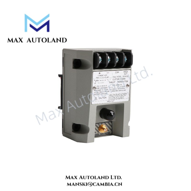
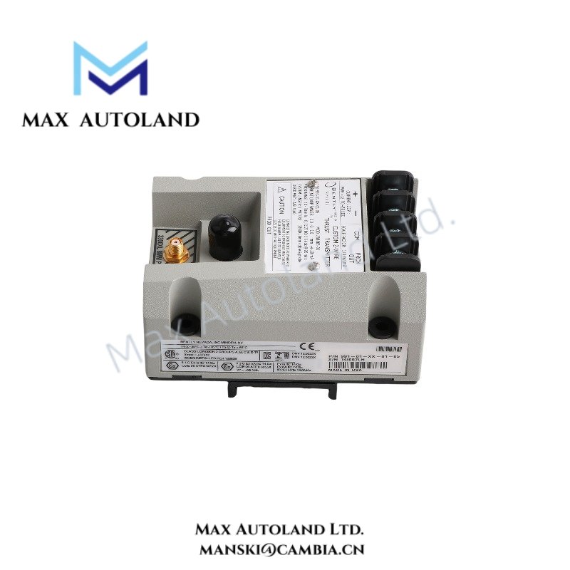
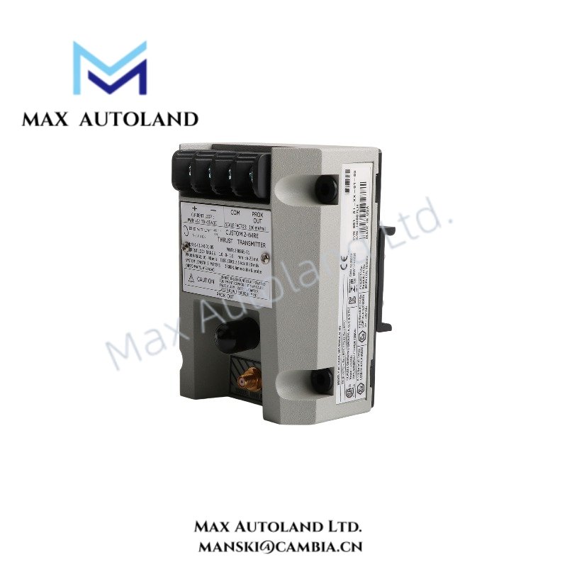
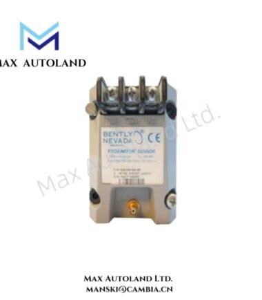
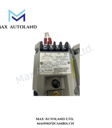
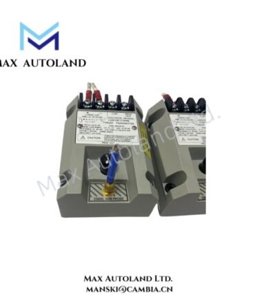
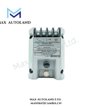
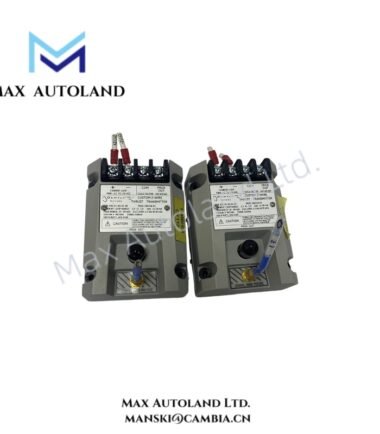
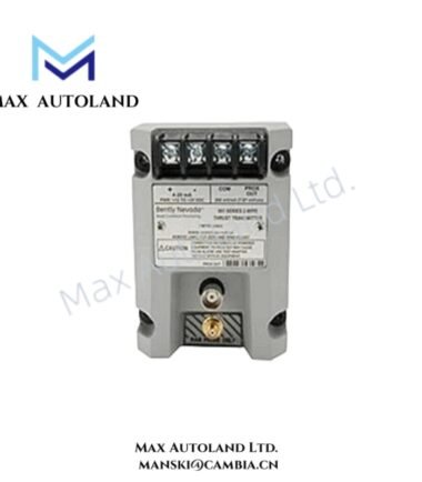
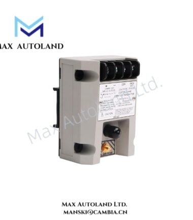
Configured for thrust displacement measurement using an eddy-current sensing chain, the Bently Nevada 991-01-XX-01-05 MOD:284318-01 (991-01-XX-01-05 991 Thrust Transmitter) converts the measured mechanical position into a 4-20 mA output signal. The unit operates from 18-30 VDC and supports 35 mm DIN-rail mounting.
Hardware Specifications
| Parameter | Specification |
|---|---|
| Model | 991-01-XX-01-05 MOD:284318-01 |
| Spare Model | 991-01-XX-01-05 |
| Brand | Bently Nevada |
| Product Type | 991 Thrust Transmitter |
| Origin | USA |
| Shipment Location | Xiamen, China |
| Weight | 0.44 kg |
| Dimensions | 7.3 x 5 x 10 cm estimated shipping size |
| Output | 4-20 mA per channel |
| Power Supply | 18-30 VDC |
| Typical Current | 50 mA |
| Resolution | 0.1% of full scale |
| Accuracy | +/-1% of reading or +/-25 um (+/-1 mil) |
| Operating Temp | -40 deg C to +85 deg C |
| Mounting | 35 mm DIN-rail clips |
| Tariff Code | 8537101190 |
| Certification / Approval | CSA Division 2, ATEX Zone 0, ATEX Zone 2, ABS maritime approval |
| Probe Configuration | 5.0 m (16.4 ft) or 7.0 m (23.0 ft), according to supplied configuration |
Eddy-Current Measurement and Thrust Signal Scaling
The 991 transmitter interfaces with an eddy-current displacement measurement chain to monitor axial thrust position. The transmitter processes the probe signal and produces a proportional 4-20 mA output for downstream monitoring or control equipment.
The specified resolution is 0.1% of full scale, while accuracy reaches +/-1% of reading or +/-25 um (+/-1 mil). Therefore, system verification should consider the complete probe, extension cable, transmitter, and receiving-input chain rather than the transmitter alone.
The supplied configuration information identifies 5.0 m and 7.0 m sensing-chain lengths. Installation should maintain the specified probe and cable configuration for correct measurement scaling.
Frequently Asked Questions (FAQ)
Q: What electrical output does the 991-01-XX-01-05 provide?
A: It provides a 4-20 mA output per channel and operates from an 18-30 VDC supply.
Q: What mounting arrangement does this configuration use?
A: The 01 suffix identifies 35 mm DIN-rail clips in the supplied configuration data.
Q: What environmental temperature range does the transmitter support?
A: The specified operating range is -40 deg C to +85 deg C.
Field Installation Guidelines
- Mount the transmitter securely on a compatible 35 mm DIN rail and verify mechanical retention before wiring.
- Route probe and signal wiring separately from high-current switching conductors where practical to reduce electrical interference.
- Use shielded instrumentation cable where the installation design requires electromagnetic noise control.
- Terminate cable shields according to the plant grounding scheme and avoid creating unintended ground loops.
- Verify the 18-30 VDC supply before energizing the transmitter.
- Confirm output-loop polarity and receiving-device input compatibility before connecting the 4-20 mA circuit.
- Maintain the specified probe and extension-cable configuration because cable length affects the measurement chain scaling.
- For hazardous-area installations, apply the applicable CSA and ATEX installation requirements for the certified configuration.
- After installation, verify the mechanical probe position, electrical connections, output signal, and receiving-system indication before placing the measurement channel into service.




Reviews
There are no reviews yet.