
Overview
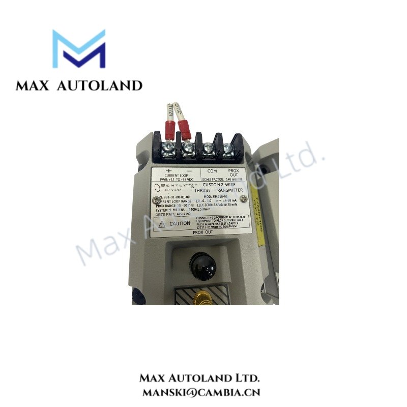
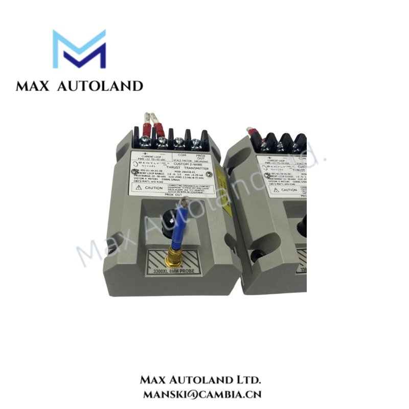
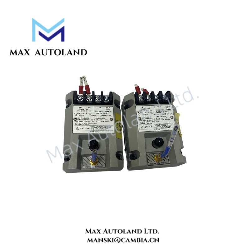
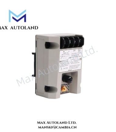
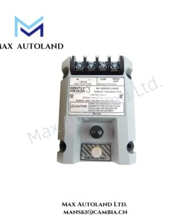
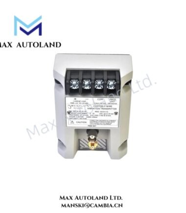
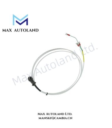
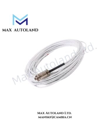
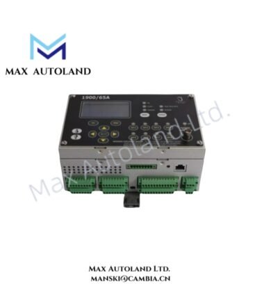
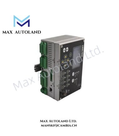
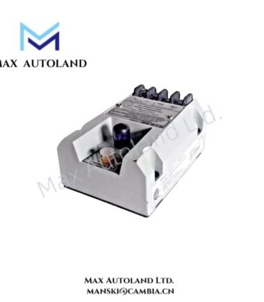
Configured for axial shaft position measurement in machinery protection signal loops, the Bently Nevada 991-01-XX-01-00 (991 Thrust Transmitter) accepts a proximity probe signal and conditions it into a proportional thrust measurement. The unit operates as a 2-wire, loop-powered transmitter and supports 5.0 m or 7.0 m system length options. The 991 interfaces with Bently Nevada 3300 NSv proximity probes. (Baker Hughes DAM)
Hardware Specifications
| Parameter | Specification |
|---|---|
| Model | 991-01-XX-01-00 |
| Product Type | 991 Thrust Transmitter |
| Brand | Bently Nevada |
| Origin | USA |
| Shipment Location | Xiamen, China |
| Weight | 0.5 kg |
| Dimensions | Estimated shipping size: 10 x 7.4 x 6 cm |
| Operating Temp | -35 deg C to +85 deg C |
| Power Consumption | +12 to +35 VDC input at transmitter terminals |
| Current Limiting | 23 mA typical |
| Output Type | 4-20 mA proportional axial displacement signal |
| System Length | 5.0 m or 7.0 m |
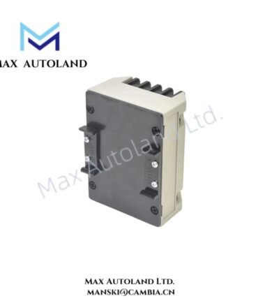
| Mounting | 35 mm DIN-rail clips |
| Agency Approval | Not required |
| Transducer Interface | 3300 NSv proximity probe |
| Construction | Potted transmitter housing |
| Supply Configuration | 2-wire, loop-powered |
Eddy-Current Probe Scaling and Thrust Signal Conditioning
The 991 transmitter conditions the eddy-current proximity probe signal into an axial displacement signal for the machinery control system. The transmitter accepts the 3300 NSv proximity probe and matching extension cable, then provides a proportional 4-20 mA output representing shaft axial position. (Baker Hughes DAM)
The probe circuit establishes the electrical measurement relationship between probe gap and shaft position. During commissioning, technicians should verify the probe gap voltage and confirm that the measured signal remains within the expected operating range before connecting the transmitter to the control loop.
The transmitter also provides PROX OUT and COM diagnostic terminals. These non-isolated terminals allow technicians to inspect the probe-related dynamic signal and gap voltage without removing the transmitter from the measurement circuit. (Baker Hughes DAM)
The Not OK/Signal Defeat function limits false high-output conditions caused by a faulty proximity probe or loose probe connection. A power-up inhibit circuit also prevents transient line conditions from producing an immediate erroneous signal. (Baker Hughes DAM)
Frequently Asked Questions (FAQ)
Q: What probe system does the 991-01-XX-01-00 support?
A: The transmitter accepts a Bently Nevada 3300 NSv proximity probe with its matching extension cable. The specified system length options are 5.0 m and 7.0 m. (Baker Hughes DAM)
Q: What electrical signal does the transmitter provide?
A: The 991 provides a 4-20 mA proportional axial displacement signal for connection to a machinery control system. It uses a 2-wire loop-powered configuration. (Baker Hughes DAM)
Q: Can technicians check the probe signal at the transmitter?
A: Yes. The transmitter provides non-isolated PROX OUT and COM terminals plus a coaxial diagnostic connection for dynamic signal and gap voltage checks. (Baker Hughes DAM)
Field Installation Guidelines
- Install the transmitter using the specified 35 mm DIN-rail clips and maintain sufficient clearance for field wiring.
- Connect the DC supply within the specified +12 to +35 VDC input range at the transmitter terminals.
- Route the proximity probe cable separately from high-voltage power conductors and high-current switching circuits where practical.
- Maintain proper cable shielding and grounding practices according to the machinery monitoring system installation design. Avoid creating unintended ground loops through shield connections.
- Verify the 3300 NSv probe wiring and extension cable before energizing the transmitter. Check connector integrity and cable continuity.
- Confirm the probe gap voltage during commissioning. A valid probe signal should remain stable while the shaft remains at the specified mechanical reference position.
- Verify the 4-20 mA loop response after connection to the control system. Confirm that the control-system input scaling matches the configured axial displacement range.
- Use the PROX OUT and COM diagnostic terminals for signal verification when troubleshooting probe wiring, gap voltage, or loop behavior.
- Do not exceed the specified supply range or current limitation. Check loop resistance and connected input impedance before commissioning.
- Protect the transmitter and cable termination from mechanical stress, excessive vibration, moisture ingress, and unintended cable movement.



Reviews
There are no reviews yet.