
Overview
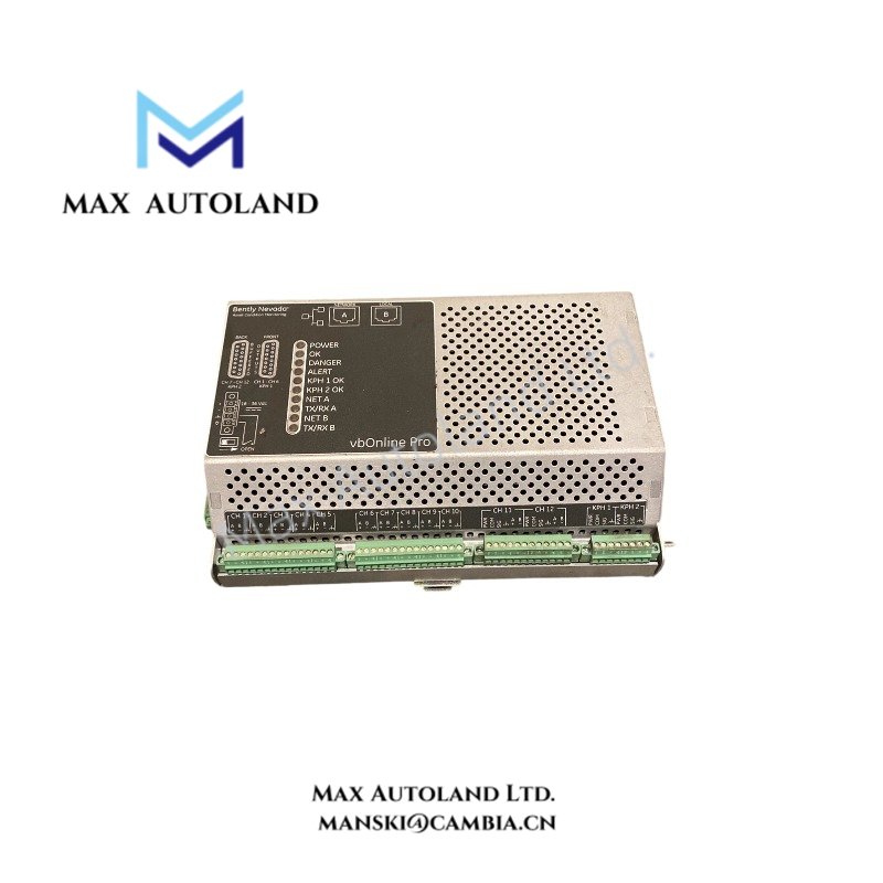
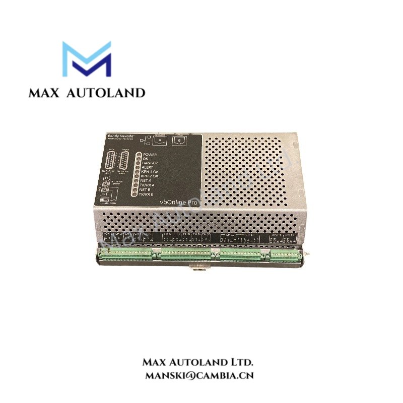
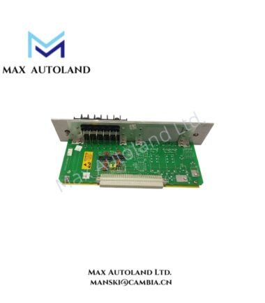
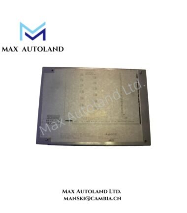
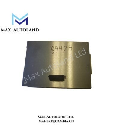
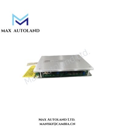
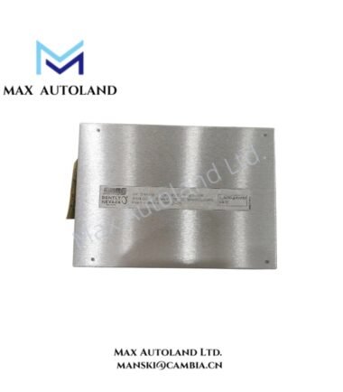
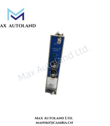
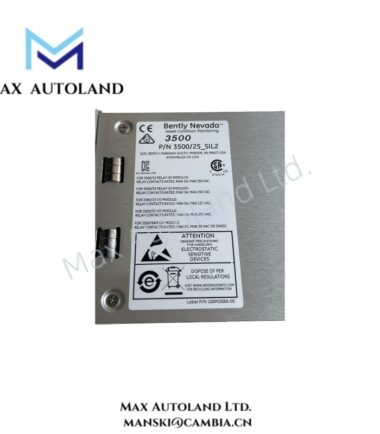
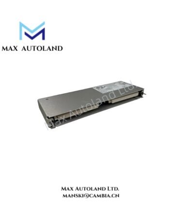
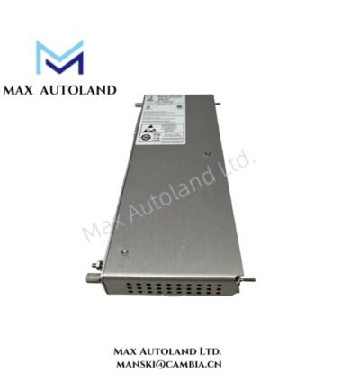
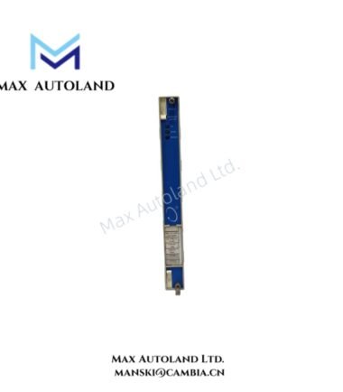
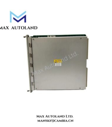
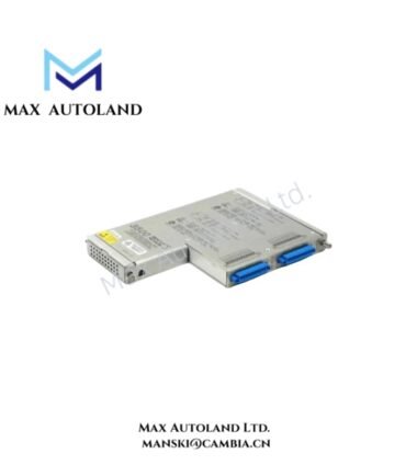
Configured for continuous vibration, temperature, and speed data acquisition in rotating machinery monitoring systems, the Bently Nevada 60M500-05-00 (60M500-05-00 Online Machinery Condition Monitoring Module) processes dynamic signals for real-time condition analysis. The unit supports 12 dynamic vibration channels, Ethernet Modbus TCP communication, local data storage, and integration with Bently Nevada System 1 software.
Suffix Breakdown & Model Matrix
The supplied documentation identifies 60M500-05-00 as a complete fixed part number. No verified suffix decomposition or option matrix is provided. Therefore, the individual digits and hyphenated fields are not assigned additional functions here.
Hardware Specifications
| Parameter | Specification |
|---|---|
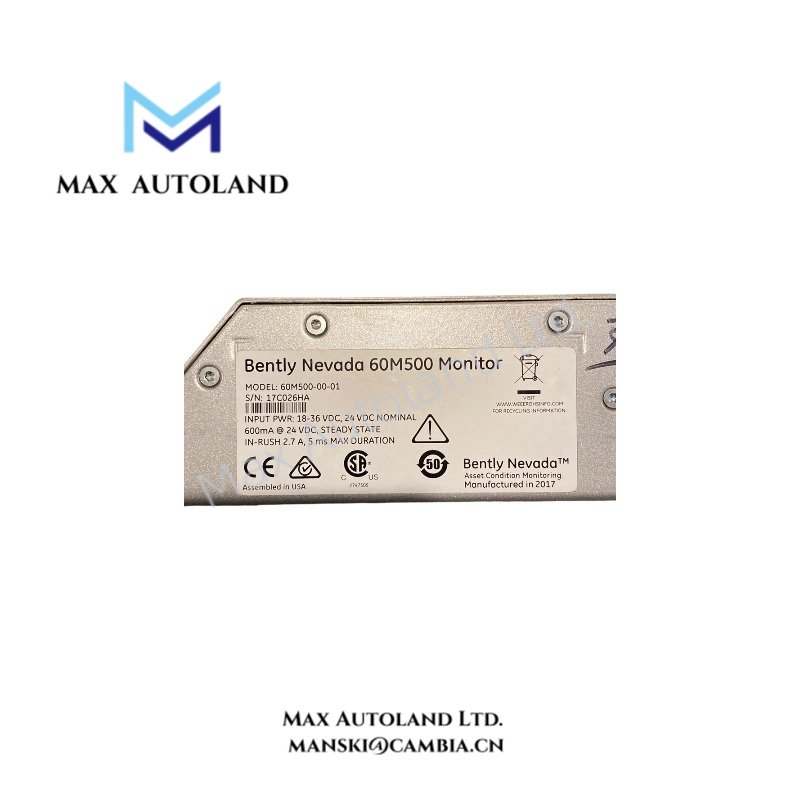
| Model | 60M500-05-00 |
| Brand | Bently Nevada |
| Manufacturer | Baker Hughes / Bently Nevada |
| Product Series | vbOnline Pro |
| Product Type | Online Machinery Condition Monitoring Module |
| Weight | Approximately 1.4 kg |
| Dimensions | 225 x 150 x 55 mm |
| Operating Temp | -40 deg C to +70 deg C |
| Storage Temp | -45 deg C to +85 deg C |
| Operating Humidity | 0% to 95% RH, non-condensing |
| Power Supply | 24 VDC +/- 10% |
| Power Consumption | Not specified in supplied data |
| Mounting | DIN rail |
| Analog Input Channels | 12 dynamic vibration channels |
| Supported Transducers | Accelerometers, velocity sensors, proximity probes |
| Additional Inputs | RTD temperature and tachometer speed inputs |
| A/D Conversion | 24-bit sigma-delta ADC |
| Frequency Range | 0.5 Hz to 10 kHz |
| Communication | Ethernet, Modbus TCP, TCP/IP |
| Software | Bently Nevada System 1 |
| Local Storage | Onboard memory and SD card slot |
| Signal Analysis | Real-time spectrum analysis (FFT) |
| Primary Function | Online machinery condition monitoring |
Rotor Dynamics and Vibration Signal Processing
The 60M500-05-00 acquires dynamic vibration signals from accelerometers, velocity sensors, or proximity probes. It also accepts temperature and tachometer inputs for correlation with machine operating conditions.
The 24-bit sigma-delta ADC provides digital conversion of the incoming measurement signals. The specified frequency range extends from 0.5 Hz to 10 kHz, supporting analysis of low-frequency mechanical behavior and higher-frequency vibration components.
For proximity probe applications, technicians should verify probe type, sensitivity, scaling, and gap-voltage requirements against the installed transducer documentation. The supplied specifications do not define a universal probe gap target for this module.
The unit performs FFT-based spectrum analysis and stores historical information through onboard memory and an SD card interface. Consequently, technicians can use time-based vibration data and event records for machinery condition trending.
Communication and System Integration
The module communicates through Ethernet using Modbus TCP and TCP/IP. It can exchange monitored data with plant automation or monitoring infrastructure through the configured network interface.
Bently Nevada System 1 software provides the specified software integration path. Before commissioning, technicians should verify the network addressing, Modbus configuration, data mapping, and System 1 compatibility for the installed software version.
The communication interface does not replace the physical transducer wiring. Therefore, technicians should verify both the analog measurement path and Ethernet communication path independently during commissioning.
Frequently Asked Questions
Q: How many dynamic vibration channels does the 60M500-05-00 provide?
A: The supplied specification identifies 12 dynamic vibration channels.
Q: What power supply does the module require?
A: The supplied specification identifies a 24 VDC supply with a +/- 10% tolerance. It does not provide a power consumption value.
Q: Can the module accept proximity probe signals?
A: Yes. The supplied specifications list proximity probes among the supported vibration transducer types. The exact probe sensitivity, scaling, and installation parameters must match the applicable transducer documentation.
Field Installation Guidelines
- Install the 60M500-05-00 on the specified DIN rail and provide sufficient clearance for field wiring and maintenance access.
- Verify the 24 VDC supply polarity and specified supply tolerance before energizing the unit. Do not connect an unverified power source.
- Identify each vibration, RTD, and tachometer channel before termination. Record the channel assignment and connected transducer type.
- Route low-level vibration and temperature signal wiring separately from high-current power cables and other high-noise conductors.
- Connect cable shields according to the plant grounding standard. Avoid multiple unintended shield-to-ground paths that can introduce ground-loop currents.
- For proximity probe installations, verify probe polarity, signal scaling, cable continuity, and the applicable probe gap condition before enabling data acquisition.
- Connect the Ethernet interface only after confirming the assigned network parameters. Verify IP addressing, Modbus TCP configuration, and communication mapping before integrating the module with supervisory software.
- Confirm the RTD and tachometer wiring separately from the dynamic vibration channels. Check signal polarity and channel configuration against the approved wiring documentation.
- Verify the measured frequency range and acquisition configuration before conducting FFT analysis. Confirm that the configured measurement settings correspond to the monitored machine and transducer.
- After commissioning, compare vibration, temperature, and speed measurements with known machine operating conditions. Record the initial measurement state for subsequent condition trending.

Reviews
There are no reviews yet.