
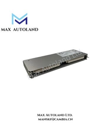
Overview
Hardware Specifications
| Parameter | Specification |
|---|---|
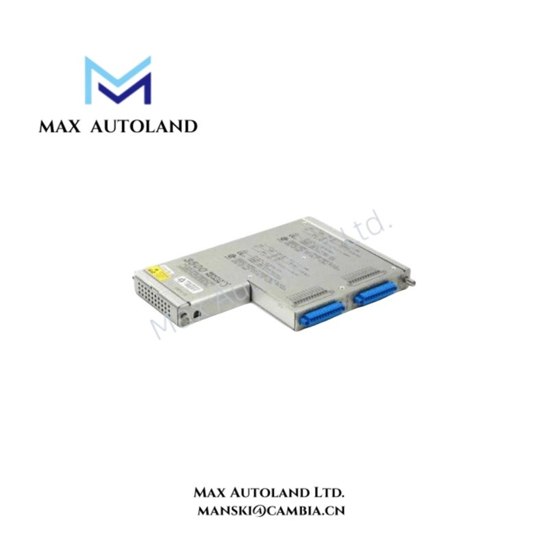
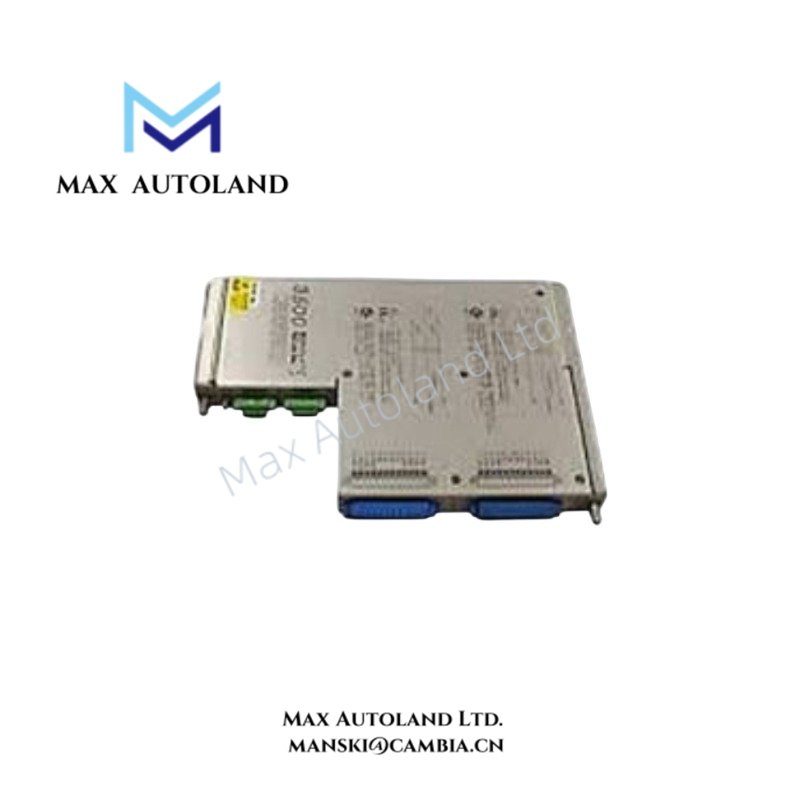
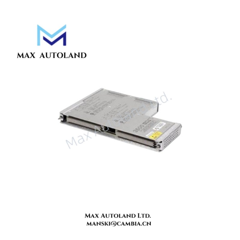
| Model | 136751-02 |
| Brand | Bently Nevada |
| Manufacturer | Baker Hughes / Bently Nevada |
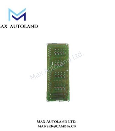
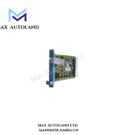
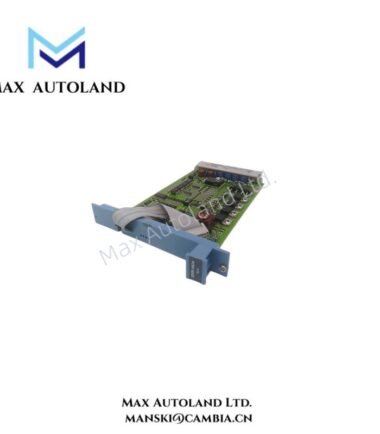
| Product Type | Isolated I/O Module |
| Origin | United States |
| Operating Temp | -40 deg C to +85 deg C |
| Power Supply | 110 VAC to 240 VAC, 50/60 Hz, system dependent |
| Power Consumption | Not specified in the supplied data |
| Communication | RS485, Modbus RTU compatible |
| Relay Outputs | Configurable alarm/trip output relays |
| Certifications | CE, ATEX |
Signal Isolation and Machinery Monitoring
The 136751-02 provides isolated I/O signal handling for machinery protection and condition monitoring applications. Electrical isolation separates connected signal circuits and can reduce the effects of ground potential differences and conducted electrical noise.
The supplied specification identifies RS485 communication with Modbus RTU compatibility. Relay outputs are described as configurable alarm/trip outputs for system-level alarm or trip functions.
For Bently Nevada monitoring applications, field signal integrity depends on correct termination, cable routing, shielding, and grounding. Signal wiring should be separated from high-current power conductors and other noise-producing circuits where practical.
Frequently Asked Questions
Q: Does the 136751-02 provide electrical isolation between I/O circuits?
A: Yes. The supplied product description identifies the 136751-02 as an isolated I/O module designed to provide signal isolation between connected circuits.
Q: What communication interface is specified for the 136751-02?
A: The supplied data specifies RS485 communication with Modbus RTU compatibility.
Q: What type of output is specified?
A: The supplied data identifies configurable relay outputs for alarm and trip functions.
Field Installation Guidelines
Install the module only in a compatible Bently Nevada system and verify the system-specific wiring documentation before energizing the circuit.
Route signal and communication cables separately from high-voltage and high-current conductors where practical. Maintain appropriate separation from sources of electromagnetic interference.
Connect cable shields according to the applicable system grounding design. Avoid creating unintended ground loops through multiple shield termination points unless the system documentation specifically requires them.
Verify field wiring polarity, termination, relay connections, and RS485 communication connections before applying power. Confirm the required system voltage and frequency because the supplied power specification is system dependent.
Do not infer mounting dimensions, terminal assignments, internal power consumption, or field wiring pinouts from the part number alone. Use the applicable Bently Nevada hardware documentation for those parameters.




Reviews
There are no reviews yet.