
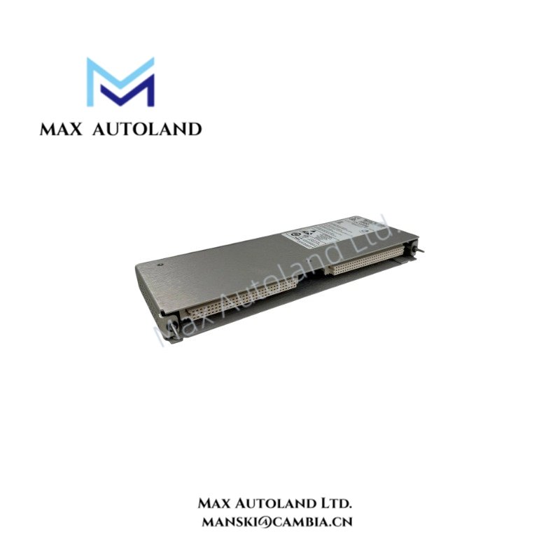
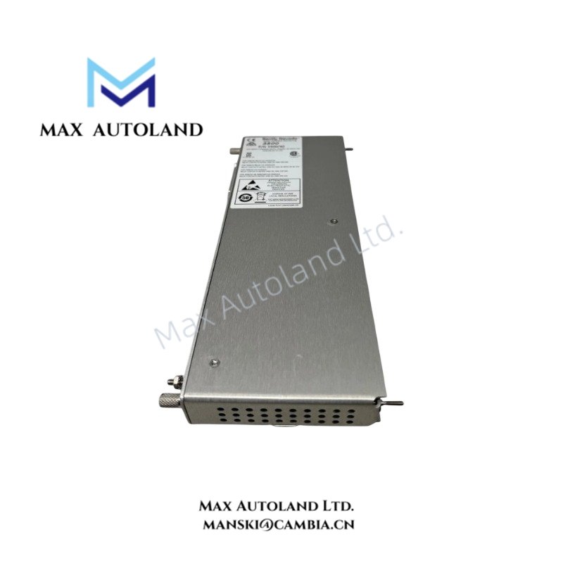
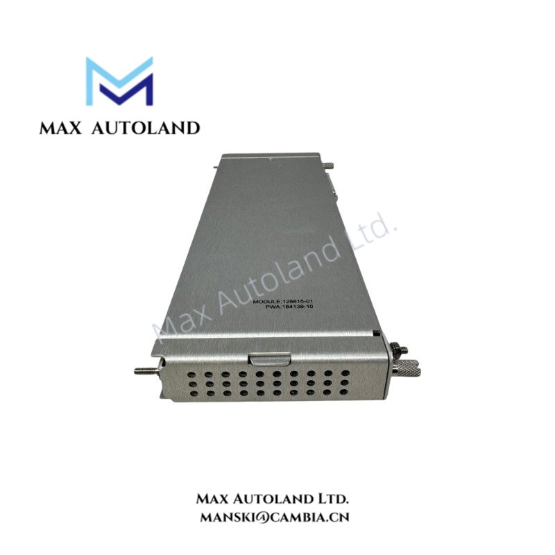
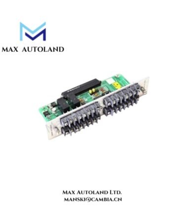
Overview
Hardware Specifications
| Parameter | Specification |
|---|---|
| Model | 184139-10 |
| Brand | Bently Nevada |
| Product Type | Proximitor I/O Module |
| Compatible System | Bently Nevada 3500 Machinery Protection System |
| Associated Monitor | 3500/40 Proximitor Monitor |
| Input Type | Proximity transducer signals |
| Probe Compatibility | Compatible proximity transducer and extension cable circuits |
| Signal Application | Vibration, shaft position, and rotor dynamics monitoring |
| Mounting | 3500 rack I/O position |
| Origin | United States |
Eddy-Current Probe Signal Interface
The 184139-10 interfaces proximity transducer circuits used for non-contact shaft measurement. In a typical 3500 monitoring channel, the probe and extension cable form the field sensing circuit, while the I/O hardware routes the associated electrical signals to the monitor.
For eddy-current proximity systems, correct probe and extension-cable matching is required to maintain the intended electrical characteristics of the measurement loop. Probe gap voltage and signal amplitude should be verified at the appropriate test points during commissioning.
Frequently Asked Questions
Q: What type of field signal does the 184139-10 interface?
A: It interfaces proximity transducer circuits used for shaft vibration, position, and related rotor-dynamic measurements.
Q: Is the 184139-10 a standalone proximity probe?
A: No. It is an I/O module associated with the 3500 monitoring architecture. The proximity probe and extension cable form the field sensing portion of the measurement circuit.
Q: Can any proximity probe be connected to this module?
A: Probe, extension cable, I/O module, and monitor compatibility must be verified as a complete channel configuration. The supplied data identifies compatibility with standard Bently Nevada proximity transducer circuits but does not define a universal probe list.
Field Installation Guidelines
- Install the module in the designated I/O position of a compatible 3500 rack.
- Verify the module part number against the required 3500 monitor channel configuration before wiring.
- Use the specified proximity probe and extension cable combination for the measurement channel.
- Keep proximity signal wiring separated from high-voltage power and high-current switching conductors.
- Maintain cable shielding and termination practices consistent with the 3500 installation documentation.
- Verify probe polarity, cable connections, and channel identification before energizing the monitoring system.
- Check the proximity channel output and probe gap condition during commissioning before placing the machinery protection channel into service.
- Do not infer operating temperature, power consumption, dimensions, or installation torque values when these parameters are not provided by the source data.


Reviews
There are no reviews yet.