
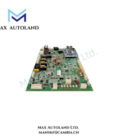
Overview
Suffix Breakdown & Model Matrix
| Code | Specification |
|---|---|
| 3500/25 | Enhanced Keyphasor Module base model |
| SIL2 | SIL 2 functional safety configuration |
| 01 | 2-channel half-height module configuration |
| 01 | Internal termination I/O configuration |
| R0 | Product revision designation |
Hardware Specifications
| Parameter | Specification |
|---|---|
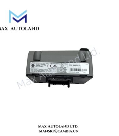
| Model | 3500/25-SIL2-01-01-R0 |
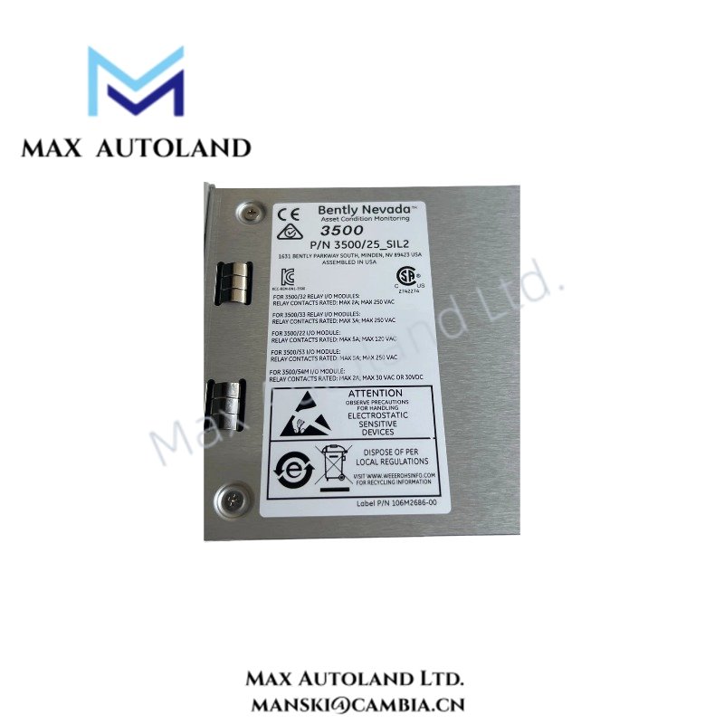
| Brand | Bently Nevada |
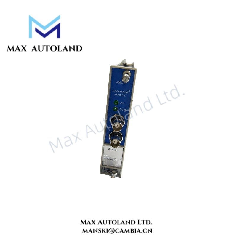
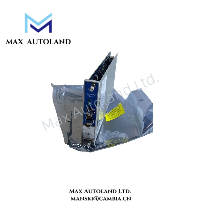
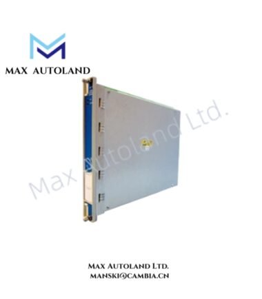
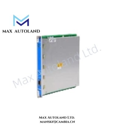
| Product Type | Enhanced Keyphasor Module |
| System | 3500 Machinery Protection System |
| Safety Rating | SIL 2, IEC 61508 functional safety |
| Number of Channels | 2 |
| Module Format | Half-height |
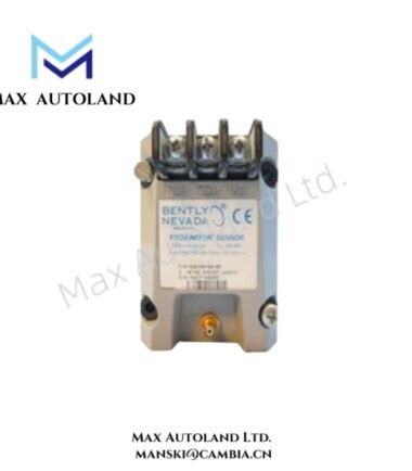
| Input Type | Proximity probe or magnetic pickup signals |
| Signal Input Range | 1 to 1,200,000 cpm (0.017 to 20 kHz) |
| Signal Output Range | 1 to 99,999 cpm (0.017 to 1667 Hz) |
| I/O Type | Internal terminations |
| Power Consumption | 3.2 W typical |
| Operating Temp | -30 deg C to +65 deg C |
| Storage Temp | -40 deg C to +85 deg C |
| Dimensions | 119.9 mm x 24.4 mm x 256.5 mm |
| Weight | Main module: 0.34 kg; I/O module: 0.46 kg |
Keyphasor Signal Processing
The module receives periodic shaft-reference signals from proximity probes or magnetic pickups. It conditions these signals into Keyphasor pulses for machinery speed tracking and phase-reference processing.
The input range extends from 1 to 1,200,000 cpm, while the specified output range extends from 1 to 99,999 cpm. Therefore, the module supports both low-speed reference signals and high-speed rotating machinery applications within its stated electrical range.
For eddy-current probe installations, technicians should verify probe scaling and signal polarity against the associated transducer specifications. In addition, gap voltage validation should use the transducer manufacturer’s specified target, such as the commonly applied -10 VDC reference for Bently Nevada proximity systems when applicable. Correct signal conditioning supports subsequent rotor dynamics and phase-angle measurements performed by connected 3500 monitor modules.
Frequently Asked Questions
Q: What signal sources can the 3500/25-SIL2-01-01-R0 accept?
A: It accepts signals from proximity probe transducers or magnetic pickups and converts the periodic input into Keyphasor reference pulses.
Q: How many channels does this configuration provide?
A: This configuration provides 2 channels in a half-height module format.
Q: What is the specified signal input frequency range?
A: The specified input range is 1 to 1,200,000 cpm, equivalent to 0.017 to 20 kHz.
Field Installation Guidelines
- Install the module only in the designated 3500 rack position specified by the system documentation.
- Verify the module identification and I/O configuration before connecting field wiring.
- Route Keyphasor signal wiring separately from high-current and high-voltage conductors where practical.
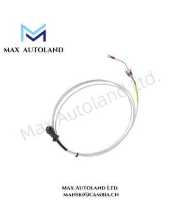
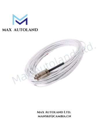
- Use appropriate shielded instrumentation cable for probe and pickup signal circuits.
- Terminate cable shields according to the approved 3500 system grounding design to reduce electromagnetic interference.
- For eddy-current probe circuits, verify probe polarity, cable continuity, and gap voltage before placing the channel into service.
- Confirm that the connected transducer type matches the configured input application.
- Do not remove or insert the module under power unless the applicable 3500 rack documentation explicitly permits hot-swap operation.
- After installation, verify the Keyphasor pulse response and measured speed against the known machine operating condition.
- Record channel wiring, transducer identification, and installation configuration for subsequent maintenance.
Reviews
There are no reviews yet.