

Overview
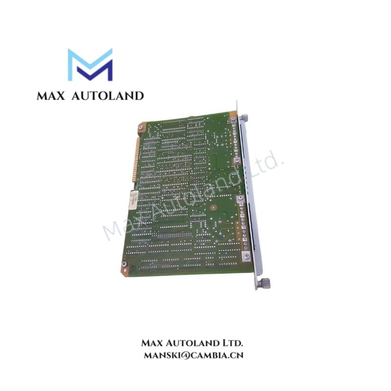
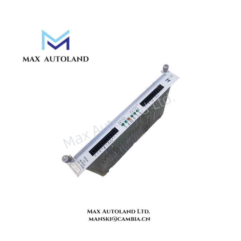
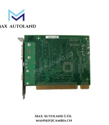
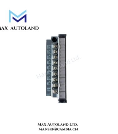
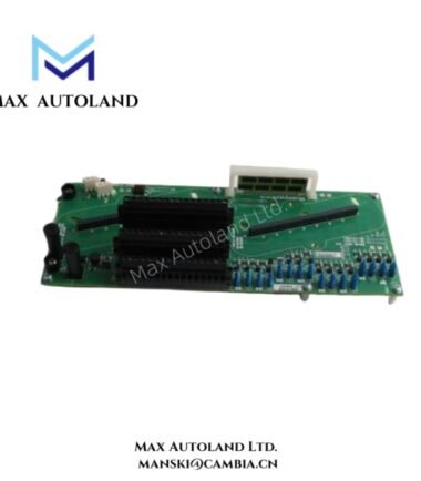
Configured for serial communication interfacing between IPC 620/621 PLC processors and external field or supervisory devices in Honeywell IPC 620/621 PLC system,the Honeywell 621-9938 (621-9938 Serial I/O module) provides direct physical/electrical execution.
Suffix Breakdown & Model Matrix
No officially published suffix segmentation or functional coding structure is defined for 621-9938 within available hardware documentation. The part number is treated as a fixed ordering identifier without publicly disclosed sub-field decoding.
Hardware Specifications
| Parameter | Specification |
|---|---|
| ModelBrand | Honeywell 621-9938 |
| Origin | United States (Manufacturer: Honeywell) |
| Weight | 0.7 kg |
| Dimensions | 3.8 cm x 26.7 cm x 16.5 cm |
| Module Type | Serial I/O Communication Module |
| System Compatibility | Honeywell IPC 620 / IPC 621 PLC platform |
| Interface Type | Serial communication (RS-232C / RS-422 / RS-485 dependent configuration) |
| Redundancy Support | Dual redundant system architecture support |
| Channel Capacity | 8 / 16 / 32 point configuration variants |
Process Control Serial Communication Characteristics (Honeywell DCS Binding)
The Honeywell 621-9938 implements serial data exchange within Honeywell process control architecture, supporting deterministic data transfer between controller backplane logic and external serial endpoints. Electrical signaling is typically implemented via configurable RS-232/RS-485 physical layers with isolation barriers for channel-to-channel noise rejection. Integration behavior aligns with distributed control system (DCS) communication models, where 4-20 mA loop instrumentation data may be logically mapped through higher-level protocol translation layers. The module supports structured communication framing for industrial ASCII or protocol-encapsulated data streams depending on firmware revision and system configuration.
Frequently Asked Questions
Q: Can the 621-9938 module be hot-swapped under live system conditions?
A: Hot-swap capability is dependent on IPC 620/621 rack design and system redundancy configuration. In standard practice, removal under energized backplane conditions requires system-level redundancy and controlled maintenance mode.
Q: Does the module introduce deterministic latency on serial transmission?
A: Communication latency is governed by backplane scheduling and selected serial baud rate. No fixed latency value is defined at module level; timing is system configuration dependent.
Q: How is redundancy handled in dual system configurations?
A: The module supports redundant pairing within IPC 620/621 architectures, with failover behavior controlled by the primary system controller and backplane arbitration logic.
Field Installation Guidelines
Install module only in compatible IPC 620/621 chassis slots with verified backplane alignment. Ensure all serial wiring is routed using shielded twisted pair cabling for RS-485 configurations, with shield termination at a single-point earth ground to reduce ground loop interference. Maintain separation between signal wiring and high-voltage conductors. Verify connector seating depth and mechanical locking before energizing system backplane. Avoid installation in energized racks unless redundancy architecture explicitly supports live insertion procedures defined by system documentation.



Reviews
There are no reviews yet.