
Overview
Hardware Specifications
| Parameter | Specification |
|---|---|
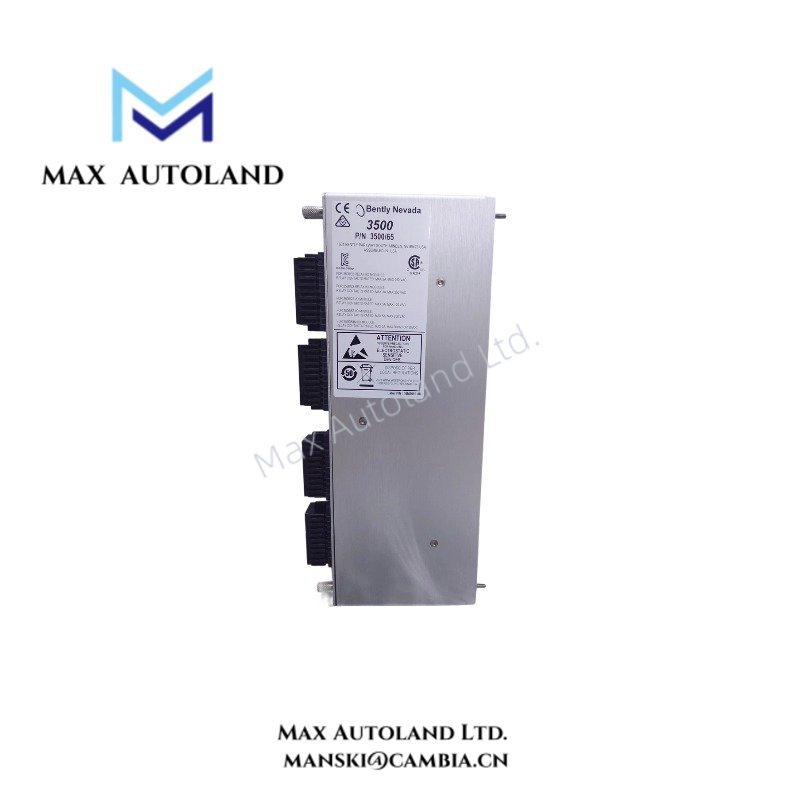
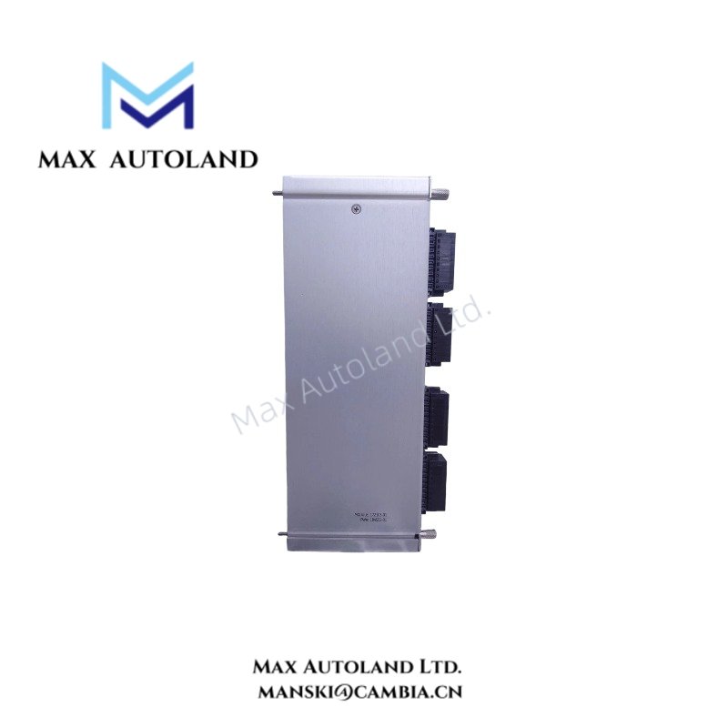
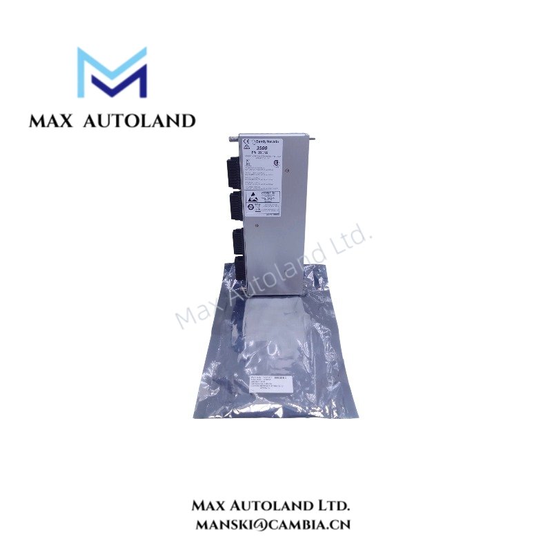
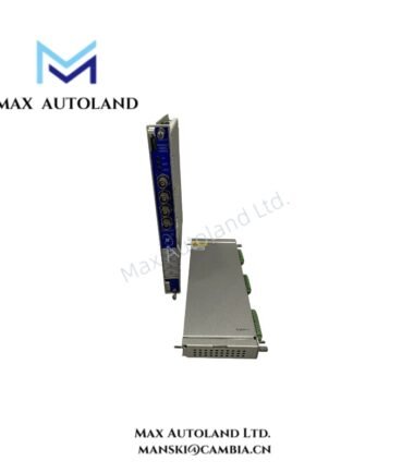
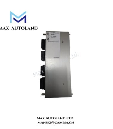
| Model | 3500/65 |
| Brand | Bently Nevada |
| Product Type | 16-Channel Temperature Monitor Module |
| Series | Bently Nevada 3500 Series |
| Factory Part/Assembly Number | 184469-01 |
| Channel Capacity | 16 independent temperature input channels |
| Input Impedance | Greater than 1 Mohm per lead input |
| Supported Thermocouples | Type E, Type J, Type K, Type T |
| Supported RTDs | 100 ohm 3-wire and 4-wire platinum, alpha = 0.00385 and alpha = 0.00392 |
| Nickel RTD | 120 ohm 3-wire and 4-wire |
| Copper RTD | 10 ohm 3-wire and 4-wire |
| RTD Excitation Current | 913 +/- 7 uA at 25 deg C per transducer |
| Resolution | 1 deg C or 1 deg F |
| Accuracy | +/- 3 deg C at +25 deg C; +/- 5.4 deg F at +77 deg F |
| Cold Junction Compensation | +/- 2 deg C at +25 deg C; +/- 3.6 deg F at +77 deg F |
| Alarm Setpoints | Software-programmable Alert and Danger thresholds for each channel |
| Alarm Adjustment Range | 0% to 100% of full scale |
| Setpoint Accuracy | Within 0.13% of the desired value |
| Alert Delay | 1 to 60 seconds, 1-second increments |
| Danger Delay | 1 to 60 seconds, 0.5-second increments |
| Power Consumption | 3 W nominal |
| Operating Temp | -30 deg C to +65 deg C |
| Storage Temp | -40 deg C to +85 deg C |
| Relative Humidity | Up to 95%, non-condensing |
| Dimensions | 241.3 mm x 24.4 mm x 241.8 mm |
| Dimensions in Inches | 9.50 in x 0.96 in x 9.52 in |
| Weight | 0.91 kg (2.0 lb) |
Bently Nevada Temperature Signal Processing
The 3500/65 accepts temperature signals from RTDs and isolated-tip thermocouples. The module conditions each input and converts the measured signal into temperature data for monitoring and alarm evaluation.
For thermocouple channels, the module applies cold junction compensation within the specified accuracy. RTD channels use the specified excitation current and support 3-wire and 4-wire sensor configurations.
Furthermore, the 16-channel architecture allows individual temperature points to operate with separate programmable Alert and Danger thresholds. The system can therefore evaluate each monitored temperature against its assigned limits rather than applying one common threshold to all channels.
When temperature wiring shares an installation area with other machinery monitoring circuits, installers should route low-level sensor conductors separately from high-current or high-noise wiring. Proper shielding and grounding practices also help limit electrical interference at the measurement inputs.
Frequently Asked Questions
Q: Which temperature sensors can the 3500/65 accept?
A: The module accepts Type E, Type J, Type K, and Type T thermocouples. It also accepts specified 100 ohm platinum, 120 ohm nickel, and 10 ohm copper RTDs in 3-wire and 4-wire configurations.
Q: How many temperature inputs does the 3500/65 provide?
A: The module provides 16 independent temperature input channels. Each channel supports its own temperature measurement and programmable Alert and Danger alarm thresholds.
Q: What alarm timing ranges does the module provide?
A: The Alert delay can be configured from 1 to 60 seconds in 1-second increments. The Danger delay can be configured from 1 to 60 seconds in 0.5-second increments.
Field Installation Guidelines
- Verify the module part number and rack configuration before installation.
- Confirm that each RTD or thermocouple type matches the configured channel.
- Use appropriate thermocouple extension or compensating wire for the selected thermocouple type.
- Maintain correct polarity on thermocouple connections.
- Follow the specified 3-wire or 4-wire RTD connection arrangement.
- Route low-level temperature sensor wiring separately from power conductors and high-current switching circuits.
- Terminate cable shields according to the site grounding and instrumentation wiring standard.
- Avoid creating unintended ground loops through shield connections.
- Inspect terminal connections for secure mechanical engagement before energizing the rack.
- Verify sensor wiring continuity and polarity before placing each channel into service.
- Confirm temperature readings against known process or reference conditions during commissioning.
- Configure Alert and Danger thresholds only after confirming the applicable operating temperature range.
- Verify alarm delay settings during functional testing before returning the machinery protection system to normal operation.







Reviews
There are no reviews yet.