
Overview
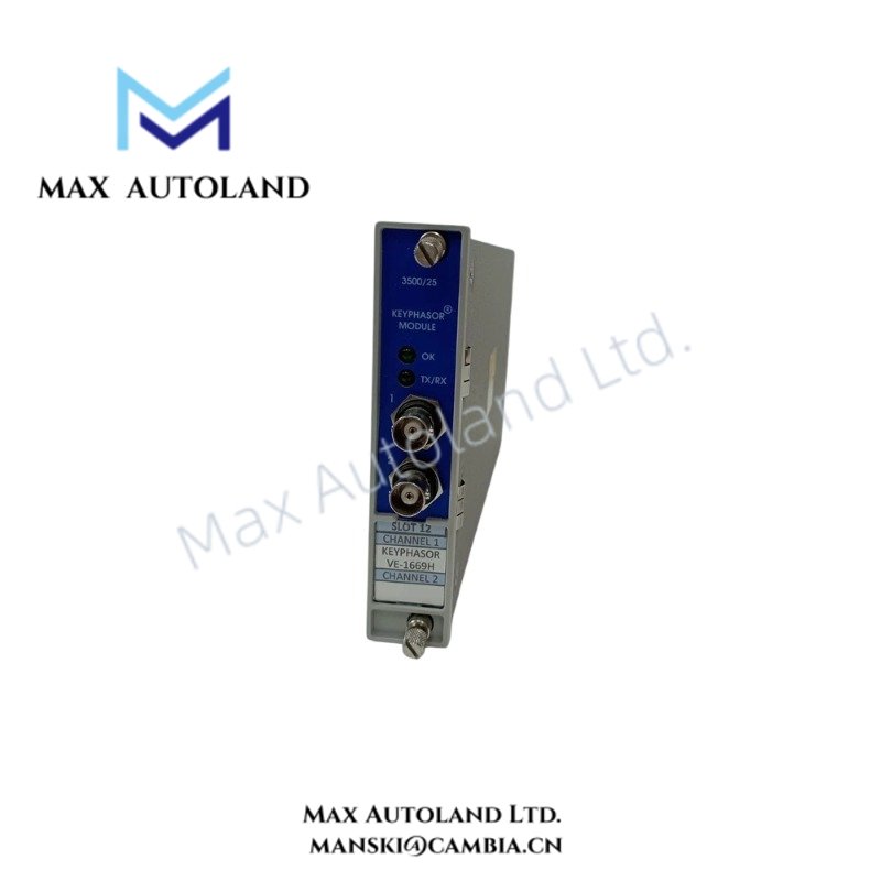
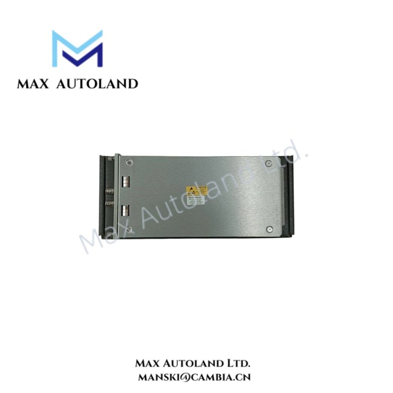
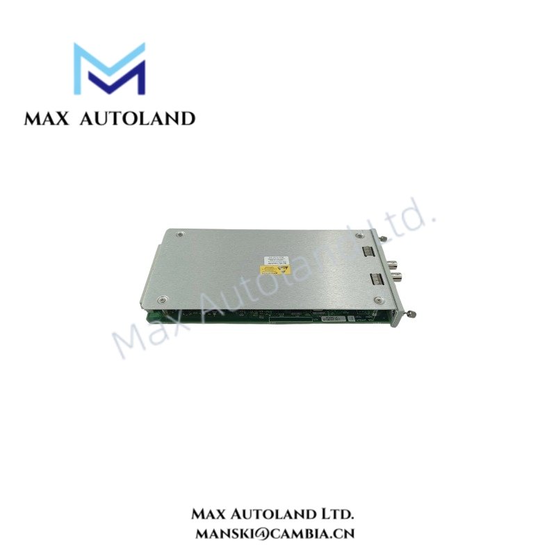
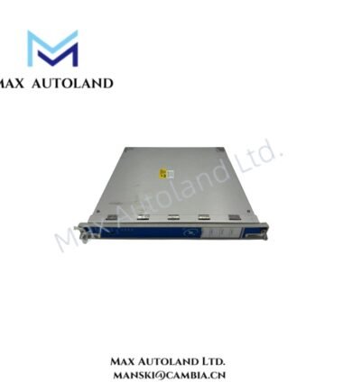
The Bently Nevada 3500/25 Enhanced Keyphasor Module, also cataloged as the 3500/25 Enhanced Keyphasor Module, operates as a dedicated hardware component for phase reference signal processing within the Bently Nevada 3500 Machinery Protection System.
Hardware Specifications
| Parameter | Specification |
|---|---|
| Model | 3500/25 Enhanced Keyphasor Module |
| Brand | Bently Nevada |
| Origin | USA |
| Product Series | 3500 Series Machinery Protection System |
| Module Type | Enhanced Keyphasor Module |
| Input Channels | 2 channels |
| Signal Function | Converts proximity probe or magnetic pickup input signals into digital Keyphasor timing signals |
| Power Consumption | 3.2 Watts nominal |
| Input Impedance | 21.8 kOhm minimum |
| Weight | 0.46 kg |
| Dimensions | 241.3 mm x 24.4 mm x 103.1 mm |
| Operating Temp | -30 deg C to +65 deg C |
| Storage Temp | -40 deg C to +85 deg C |
| Rack Position | Half-height module slot |
| Compatibility | Replaces legacy PWA 125792-01 Keyphasor module designs |
Rotor Dynamics Signal Reference Processing
The Bently Nevada 3500/25 Enhanced Keyphasor Module processes phase reference signals used for rotor dynamics measurements. The module receives input from eddy-current proximity probes or magnetic pickups and generates digital Keyphasor pulses for synchronization with monitor modules.
Furthermore, the module supports phase-related vibration analysis functions, including 1X phase measurement, vibration vector calculations, and machine speed reference tracking. The Keyphasor input architecture maintains signal timing accuracy by applying input conditioning and noise rejection techniques.
For eddy-current probe applications, the module operates with the 3500 system signal chain to support probe scaling and gap voltage validation. The standard Bently Nevada monitoring architecture uses gap voltage targets near -10 VDC for verifying correct probe operating conditions.
The module also supports rotor dynamics applications where accurate phase reference data is required for shaft vibration analysis, balancing procedures, and transient event evaluation.
Frequently Asked Questions
Q: Can the 3500/25 Enhanced Keyphasor Module replace older Keyphasor modules?
A: Yes. The 3500/25 module maintains backward-compatible mechanical and electrical interfaces with legacy Keyphasor module designs, including PWA 125792-01 replacement applications.
Q: How many Keyphasor signals can a 3500 system process with this module?
A: A standard configuration supports up to 4 Keyphasor signals. A paired module configuration can increase capacity up to 8 signals.
Q: Does the 3500/25 support redundant Keyphasor configurations?
A: Yes. The module supports redundant applications where two Keyphasor modules operate in parallel to provide primary and secondary timing reference signals.
Field Installation Guidelines
Install the 3500/25 module in the designated half-height Keyphasor slot position within the 3500 rack. Verify that the rack backplane connection is fully seated before system operation.
Connect proximity probe or magnetic pickup wiring according to the approved 3500 system wiring configuration. Use shielded signal cables for Keyphasor inputs and terminate cable shields according to the site grounding practice.
Keep Keyphasor signal cables separated from high-current power conductors and switching circuits to reduce electrical interference. Verify probe polarity, signal amplitude, and gap voltage conditions before enabling machine monitoring functions.
Confirm that the module firmware and rack configuration settings match the installed 3500 system requirements before commissioning.




Reviews
There are no reviews yet.