
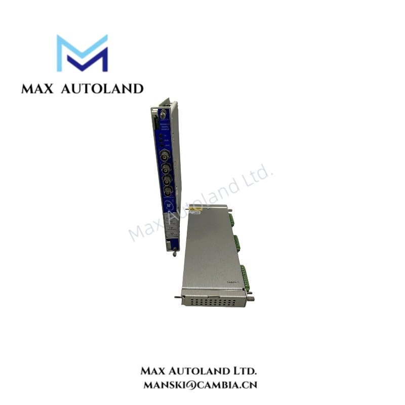


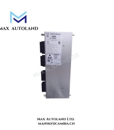
Overview
Hardware Specifications
| Parameter | Specification |
|---|---|
| Model | 3500/70M |
| Part Number | 136449-09 |
| Brand | Bently Nevada |
| Product Type | Reciprocating Impulse Velocity Monitor |
| System | 3500 Machinery Protection System |
| Number of Channels | 4 |
| Input Configuration | 1 to 4 transducer inputs |
| Input Types | Proximity or seismic probe inputs |
| Supported Measurements | Impulse Acceleration, Acceleration 2, Recip Velocity, Low Frequency Recip Velocity |
| Input Impedance – Acceleration | 10 kOhm |
| Input Impedance – Velocity | Greater than 1 MOhm |
| Special Inhibit Input | Contact closure, 5 VDC at 390 uA |
| Sensitivity – Impulse / Acceleration 2 | 0.51 to 11.72 mV/(m/s2), or 5 to 115 mV/g |
| Sensitivity – Recip Velocity / LF Recip Velocity | 3.54 to 22.64 mV/(mm/s), or 90 to 575 mV/(in/s) |
| Transducer Power | -22 VDC minimum, 40 mA maximum |
| Recorder Outputs | 4-20 mA |
| Recorder Output Accuracy | +/- 0.05 mA |
| Maximum Recorder Load | 600 Ohm |
| Measurement Accuracy | +/- 0.33% typical, +/- 1% maximum, excluding filters |
| High-Pass Response – Impulse / Acceleration 2 | 3 to 3000 Hz |
| High-Pass Response – Recip Velocity | 1 to 400 Hz |
| Low-Pass Response – Impulse / Acceleration 2 | 30 to 30000 Hz |
| Low-Pass Response – Recip Velocity | 40 to 5500 Hz |
| Alarm Setpoint Range | 0% to 100% of full scale |
| Alarm Setpoint Accuracy | +/- 0.13% |
| Alert Time Delay | 1 to 60 seconds |
| Danger Time Delay | 0.1 to 60 seconds |
| Power Consumption | 7.7 W nominal |
| Dimensions | 241.3 mm x 24.4 mm x 241.8 mm |
| Weight | 0.91 kg |
| Operating Temp | -30 deg C to +65 deg C |
| Storage Temp | -40 deg C to +85 deg C |
| Relative Humidity | Up to 95% non-condensing |
Reciprocating Machinery Signal Monitoring
The 3500/70M processes dynamic signals from reciprocating compressor machinery and supports four selectable measurement functions. Operators configure each channel through the 3500 Rack Configuration Software, while paired channels can support two measurement functions simultaneously.
The module provides separate sensitivity ranges for impulse and acceleration measurements and for reciprocating velocity measurements. Therefore, the input conditioning can match the electrical characteristics of the connected transducer.
For vibration protection, the monitor compares measured values with programmable Alert and Danger setpoints. It also applies configurable time delays before alarm states become active. Recorder outputs provide 4-20 mA signals for external monitoring circuits.
Bently Nevada machinery monitoring applications also require correct transducer scaling and signal integrity. Consequently, technicians should verify the installed probe or seismic transducer type, polarity, sensitivity, and signal conditioning before commissioning. Where eddy-current probes form part of the measurement chain, technicians should also validate the probe gap voltage against the applicable transducer system requirements.
The 3500/70M supports integration with the 3500 Operator Display Software and System 1 Condition Monitoring and Diagnostic software. These interfaces allow configured measurement values and status information to move into the associated monitoring environment.
Frequently Asked Questions
Q: How many transducer channels does the 3500/70M 136449-09 provide?
A: The monitor provides four channels and accepts one to four supported proximity or seismic transducer inputs.
Q: Which measurement functions can the 3500/70M perform?
A: The module supports Impulse Acceleration, Acceleration 2, Recip Velocity, and Low Frequency Recip Velocity functions.
Q: What recorder output does the module provide?
A: The module provides 4-20 mA recorder outputs with +/- 0.05 mA stated accuracy and a maximum load of 600 Ohm.
Field Installation Guidelines
- Install the monitor module in the designated 3500 rack position and secure the module according to the rack installation procedure.
- Verify that the connected transducer type matches the configured input function before applying operating signals.
- Route transducer wiring separately from high-current power conductors and other high-noise signal cables where practical.
- Maintain proper cable shielding and terminate shields according to the applicable Bently Nevada system wiring practice.
- Confirm signal polarity and transducer excitation before commissioning.
- Verify configured sensitivity against the installed transducer specification.
- For eddy-current measurement chains, verify probe installation and gap voltage before enabling machinery protection functions.
- Check all Alert and Danger setpoints against the approved machinery protection configuration before placing the channel in service.
- Confirm recorder output wiring and external load compatibility before connecting the 4-20 mA circuits.
- Verify alarm delay settings and inhibit wiring during functional testing.
- Confirm communication with the 3500 Operator Display Software or System 1 environment after completing hardware commissioning.
- Do not route sensor cables through areas that can introduce mechanical damage, excessive electromagnetic interference, or ground-loop conditions.
Reviews
There are no reviews yet.