
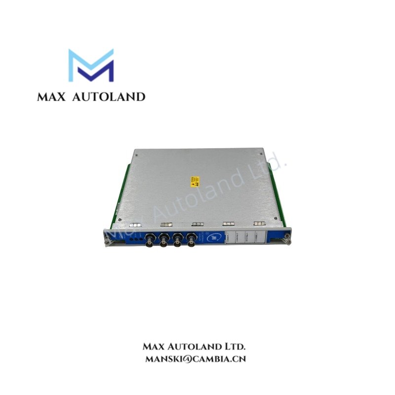
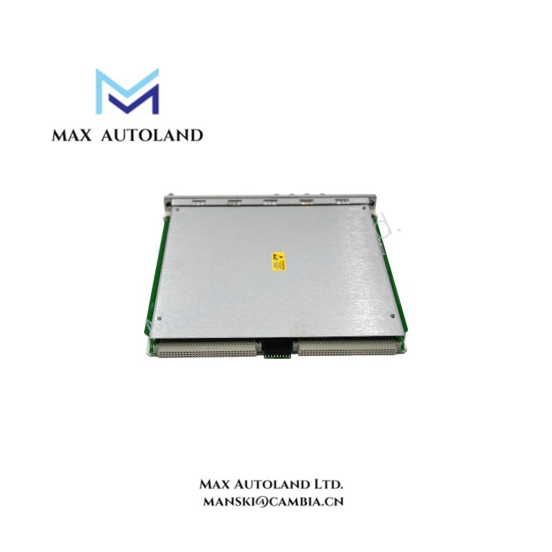
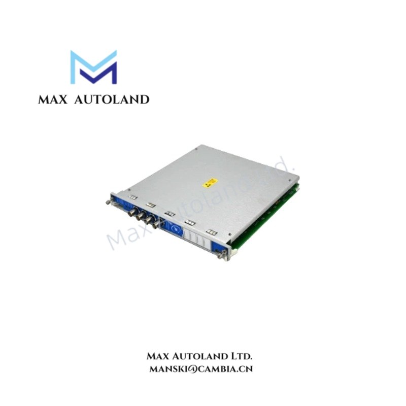


Overview
Hardware Specifications
| Parameter | Specification |
|---|---|
| ModelBrand | Bently Nevada 140734-03 |
| Origin | USA |
| Weight | Not specified (rack plug-in module, refer to 3500 chassis documentation) |
| Dimensions | Standard Bently Nevada 3500 plug-in module form factor |
| OperatingTemp | -20 degC to +65 degC (typical 3500 system envelope) |
| PowerConsumption | 7–15 W (system dependent configuration) |
| Signal Inputs | Proximity probe, velocity, accelerometer (configuration dependent) |
| Communication | 3500 rack backplane bus |
| Alarm Processing | Alert / Danger threshold logic |
| Diagnostics | Open/short detection, module self-test routines |
Eddy-Current Probe Scaling and Signal Integrity Behavior
The module supports eddy-current proximity probe interface scaling aligned with gap voltage conversion characteristics typical of Bently Nevada 3500 architecture. Input conditioning stages validate negative bias supply behavior (commonly referenced around -10 VDC probe excitation reference levels at system level) and convert dynamic shaft displacement signals into calibrated engineering units. Cross-channel interference suppression is implemented through internal signal isolation routing on the backplane, minimizing phase distortion under high vibration density environments. Rotor dynamic response tracking is maintained through continuous sampling and synchronized alarm evaluation cycles.
Frequently Asked Questions
Q: Does the 140734-03 support hot-swap operation within a live 3500 rack?
A: Hot-swap capability is dependent on rack configuration. Standard 3500 chassis designs support module replacement under controlled conditions, but signal interruption during insertion/removal is expected.
Q: What is the backplane communication dependency for this module?
A: The module relies entirely on the 3500 rack backplane for data exchange. No standalone external communication interface is present.
Q: Are firmware or configuration mismatches detectable at runtime?
A: Yes. The module performs self-diagnostics during initialization and reports configuration inconsistency via system status registers.
Field Installation Guidelines
Ensure the 3500 rack is de-energized or placed in maintenance bypass mode before insertion if system redundancy is not configured. Maintain correct module alignment with rack guide rails to avoid backplane pin stress. Shielded sensor cabling must be grounded at a single-point chassis earth reference to prevent ground loop noise. Avoid routing low-level proximity probe wiring parallel to high-power switching conductors. Verify module seating integrity after insertion to ensure full backplane connector engagement.




Reviews
There are no reviews yet.