
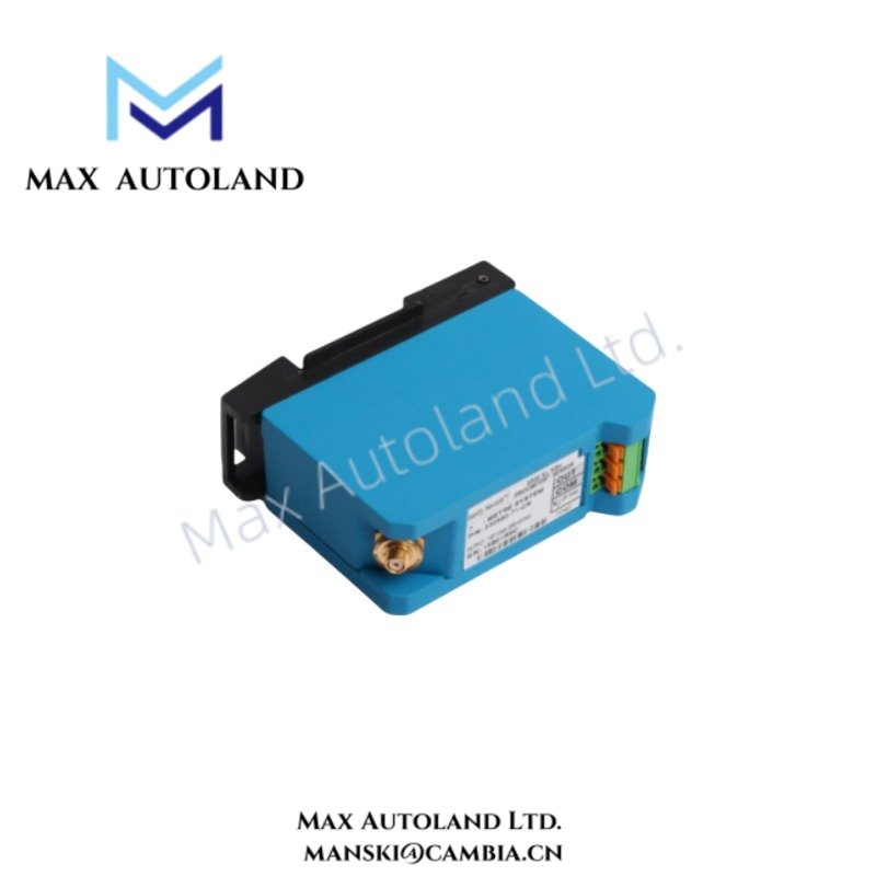
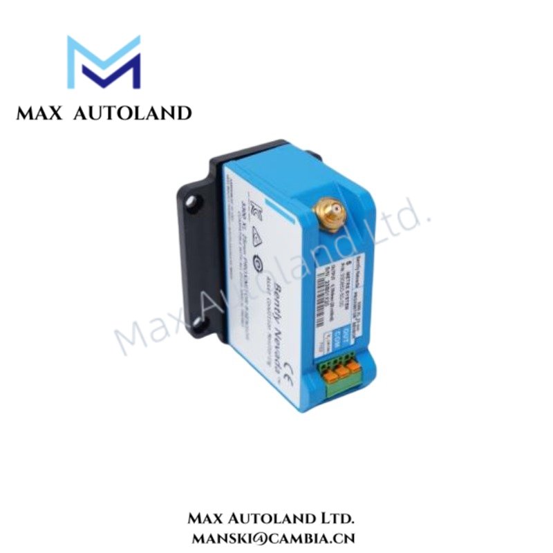
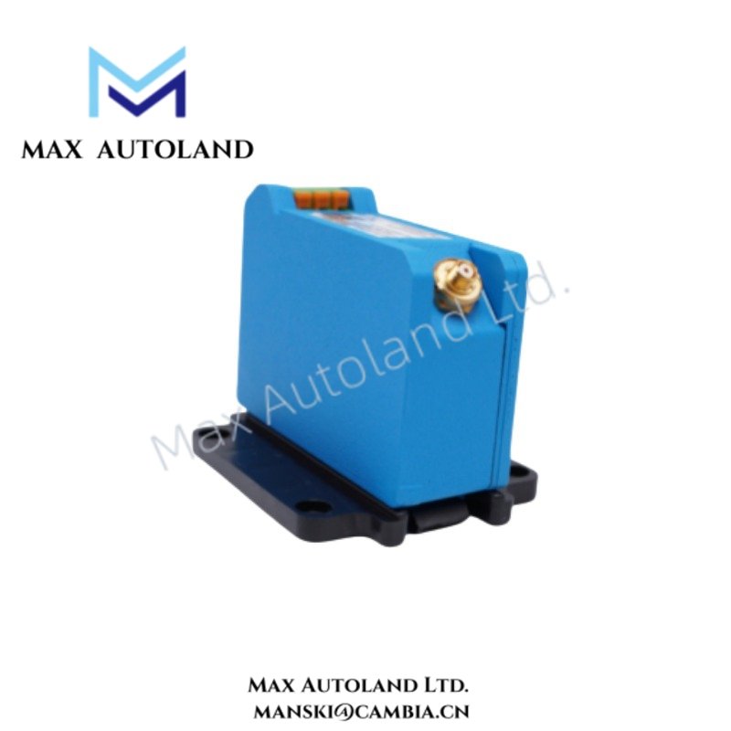

Overview
Suffix Breakdown & Model Matrix
| Code | Specification |
|---|---|
| 330180 | 3300 XL Proximitor Sensor base model |
| X1-05 | Configuration with CSA, ATEX, and IECEx approvals |
| MOD: 145004-47 | Modification identifier supplied with the listed unit |
| 11 | 1.0 m (3.3 ft) system length, DIN mount |
| 51 | 5.0 m (16.4 ft) system length, DIN mount |
| 91 | 9.0 m (29.5 ft) system length, DIN mount |
The available source data identifies 11, 51, and 91 as system-length and mounting options. It does not provide an independent mapping between the complete MOD number and these individual length selections.
Hardware Specifications
| Parameter | Specification |
|---|---|
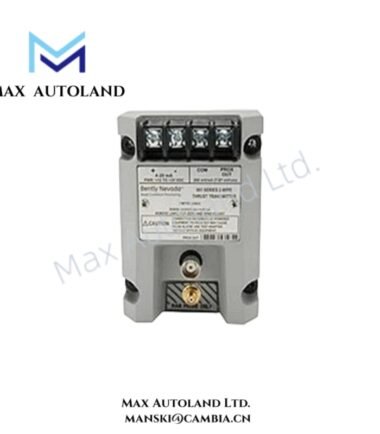
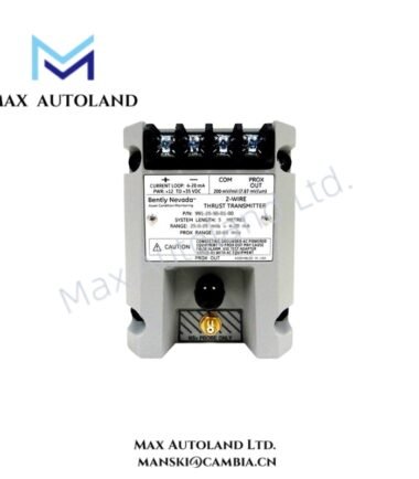
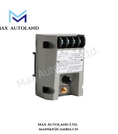
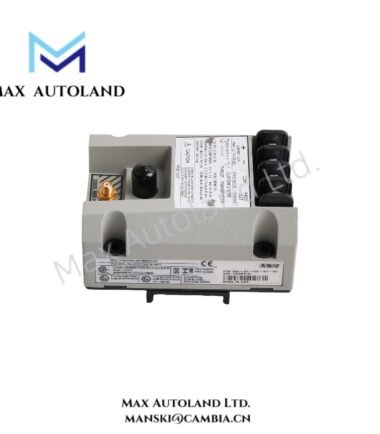
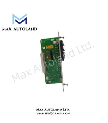
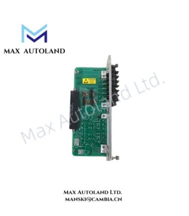
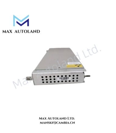
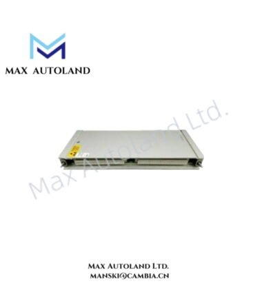
| Model | 330180-X1-05 MOD: 145004-47 |
| Brand | Bently Nevada |
| Product Type | 3300 XL Proximitor Sensor |
| Series | 3300 XL |
| Origin | USA |
| Weight | 0.25 kg |
| Operating Temp | -52 deg C to +100 deg C |
| Storage Temp | -52 deg C to +105 deg C |
| Power Consumption | Not specified |
| Mounting | DIN mount |
| System Length Options | 1.0 m, 5.0 m, 9.0 m |
| Agency Approvals | CSA, ATEX, IECEx |
| Probe Tip Material | Polyphenylene sulfide |
| Probe Case Material | AISI 303 or 304 stainless steel |
| Core Function | Eddy-current proximity probe signal conditioning |
| Tariff Code | 8537101190 |
Eddy-Current Measurement and Gap Voltage
The 3300 XL Proximitor Sensor processes the electrical signal associated with an eddy-current proximity probe. Therefore, installation requires correct probe-to-target geometry and suitable cable routing to preserve measurement integrity.
For commissioning, technicians should verify the probe gap voltage against the applicable Bently Nevada system requirements. A nominal -10 VDC gap target is commonly associated with Bently Nevada eddy-current probe systems, but the exact acceptance range must follow the applicable probe and monitor documentation.
The stainless-steel probe case and polyphenylene sulfide probe tip provide the specified mechanical materials for the sensor assembly. Furthermore, the selected 1.0 m, 5.0 m, or 9.0 m system length must match the installed probe and extension-cable configuration.
Frequently Asked Questions
Q: What mounting configuration does the listed unit specify?
A: The supplied description specifies DIN mounting. The listed system-length options are 1.0 m, 5.0 m, and 9.0 m.
Q: What environmental temperature range does the sensor support?
A: The specified operating range is -52 deg C to +100 deg C. The specified storage range is -52 deg C to +105 deg C.
Q: Which approvals are identified for the 330180-X1-05 configuration?
A: The supplied data identifies CSA, ATEX, and IECEx approvals.
Field Installation Guidelines
- Install the Proximitor Sensor on the specified DIN mounting arrangement and maintain secure mechanical retention.
- Route proximity probe wiring separately from high-current power conductors and high-noise switching circuits where practical.
- Maintain the specified probe-to-target geometry during installation and prevent mechanical movement after adjustment.
- Use appropriate shielding and grounding practices for eddy-current measurement circuits. Avoid creating unintended ground loops.
- Verify cable connections and polarity before energizing the monitoring circuit.
- During commissioning, measure and record the probe gap voltage before placing the machinery protection channel into service.
- Confirm that the selected system length corresponds to the installed probe and associated cable configuration.
- Inspect cable insulation, connector condition, and mechanical strain relief before final system acceptance.
- Apply the applicable CSA, ATEX, and IECEx installation requirements when operating the equipment in a certified hazardous-area installation.


Reviews
There are no reviews yet.