


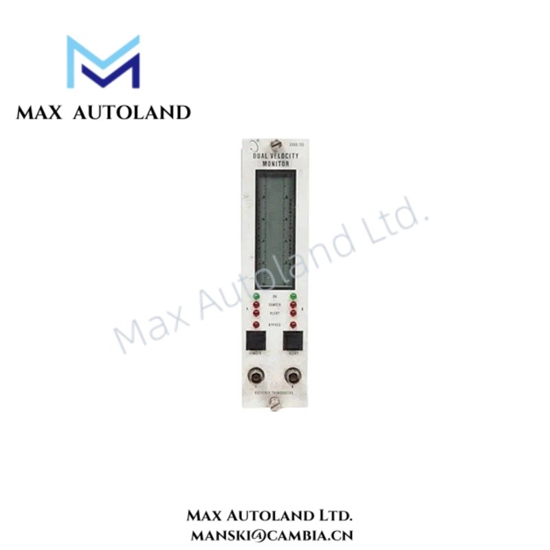
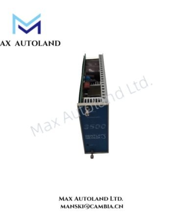
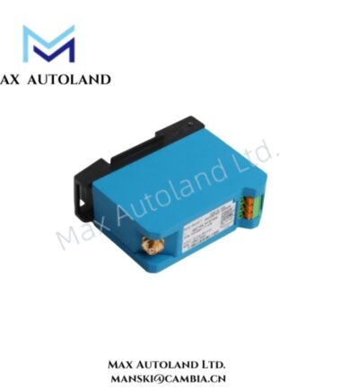
Overview
Hardware Specifications
| Parameter | Specification |
|---|---|
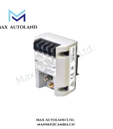
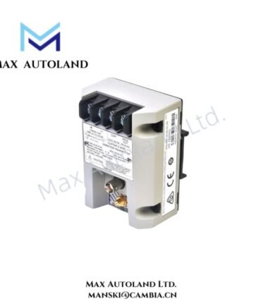
| Model | 3300/53-03-02-00-30-20-00-00-00 |
| Base Model | 3300/53 |
| Brand | Bently Nevada |
| Product Series | 3300 Series |
| Product Type | Overspeed Protection System |
| Primary Function | Overspeed detection and shutdown protection |
| Signal Type | Tachometer input signals |
| Monitoring Architecture | Two-channel or three-channel system configurations |
| Voting Logic | 1 out of 2 for two-channel configuration; 2 out of 3 for three-channel configuration |
| Relay Configuration | Normally de-energized or normally energized arrangements, depending on system configuration |
| Power Input | 95 – 125 VAC, 50/60 Hz, or 190 – 250 VAC, 50/60 Hz, depending on configured power option |
| Maximum Steady-State Current | 0.29 A at 95 – 125 VAC option; 0.15 A at 190 – 250 VAC option |
| Peak Inrush Current | 2.5 A |
| Mounting | 3300 Series rack or standalone system configuration |
| System Interface | 3300 rack interface and dedicated signal and power input module |
| Origin | USA |
| Power Consumption | AC input; exact consumption depends on configured voltage and system loading |
The published 3300/53 manual identifies the unit as an overspeed protection component with independent tachometer channels. It also specifies AC input ranges of 95 – 125 VAC and 190 – 250 VAC, with corresponding steady-state and inrush current limits. (Scribd)
Eddy-Current Tachometer Signal Processing and Rotor Dynamics
The 3300/53 uses tachometer inputs to determine shaft rotational speed and initiate overspeed protection functions. In a typical Bently Nevada installation, the tachometer signal can originate from a proximity transducer system that detects shaft movement without mechanical contact.
For eddy-current systems, probe gap voltage must remain within the calibrated operating region of the associated probe and Proximitor Sensor. A nominal -10 VDC gap reference is commonly used when validating Bently Nevada proximity probe installation, but the exact acceptance range must follow the applicable transducer documentation.
Rotor dynamics affect the pulse signal through shaft runout, mechanical eccentricity, target geometry, and installation alignment. Therefore, probe mounting, cable routing, shielding, and signal reference integrity should be verified before setting the overspeed trip point.
The 3300/53 manual specifies independent overspeed monitoring channels and voting arrangements intended to reduce the probability of a missed overspeed condition or an unwanted shutdown, depending on the selected system architecture. (Scribd)
Frequently Asked Questions (FAQ)
Q: Can the 3300/53 operate without a 3300 System Monitor or 3300 Power Supply?
A: Yes. The 3300/53 Overspeed Protection System can operate as a standalone system. It can also be installed in a 3300 rack configuration. (pdfcoffee.com)
Q: Does the 3300/53 provide two-channel and three-channel protection configurations?
A: Yes. The documented system supports two independent overspeed channels with 1 out of 2 voting, or three independent channels with 2 out of 3 voting. (Scribd)
Q: Is hot-swapping specified for the 3300/53?
A: The supplied documentation does not specify unrestricted hot-swapping. Removing the tachometer from an energized protection system can remove the associated machine protection function, so maintenance must follow the applicable 3300 installation procedure. (Scribd)
Field Installation Guidelines
- Verify the complete part number against the equipment identification label before installation.
- Confirm the selected AC input voltage matches the installed power configuration.
- De-energize applicable circuits before connecting or removing field wiring.
- Route tachometer signal wiring separately from high-current and high-voltage conductors.
- Maintain appropriate cable shielding and grounding practices for low-level tachometer signals.
- Verify probe installation, target condition, and gap voltage before commissioning an eddy-current tachometer circuit.
- Confirm the configured overspeed setpoint against the approved machinery protection design.
- Verify relay logic and interposing relay wiring before placing the shutdown circuit into service.
- Perform channel verification and functional testing after wiring changes or module replacement.
- Do not infer undocumented suffix functions from the part number alone. The detailed option coding should be checked against the applicable Bently Nevada documentation.


Reviews
There are no reviews yet.