
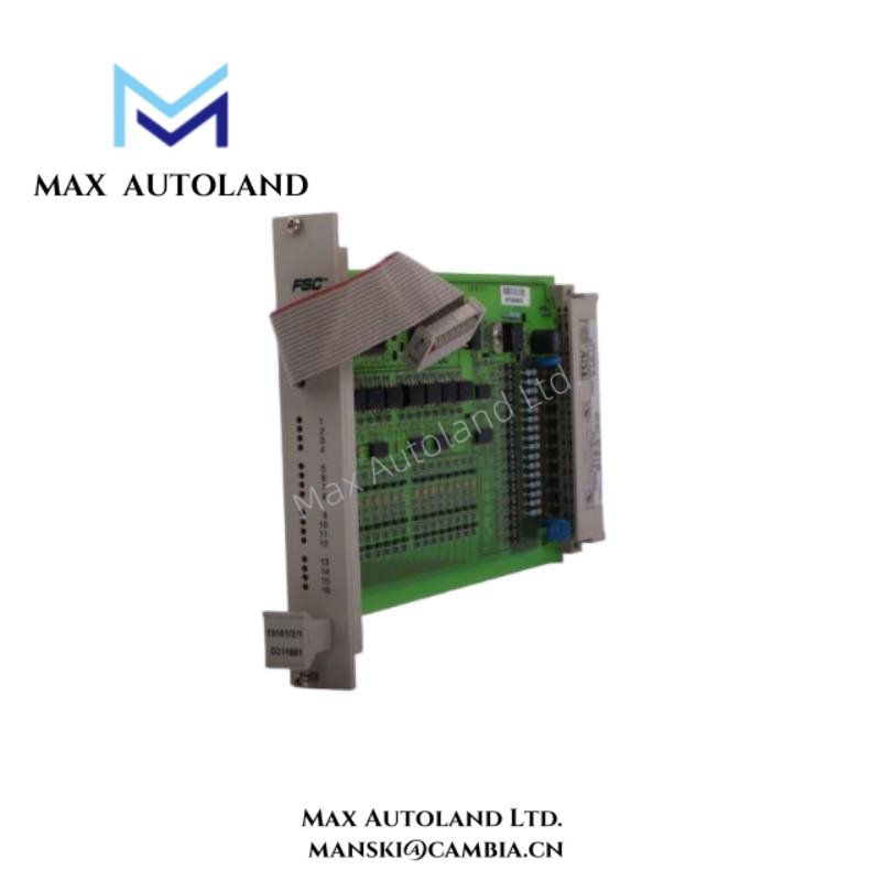
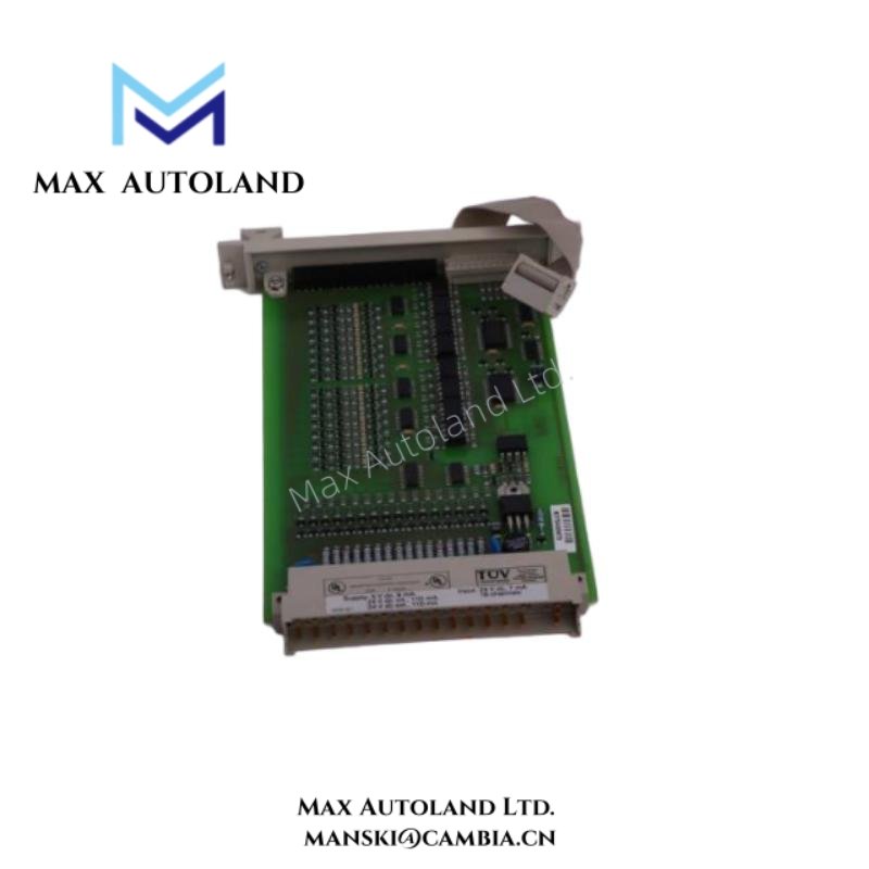
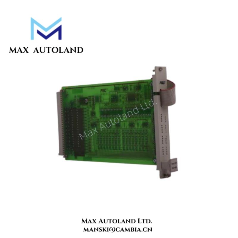
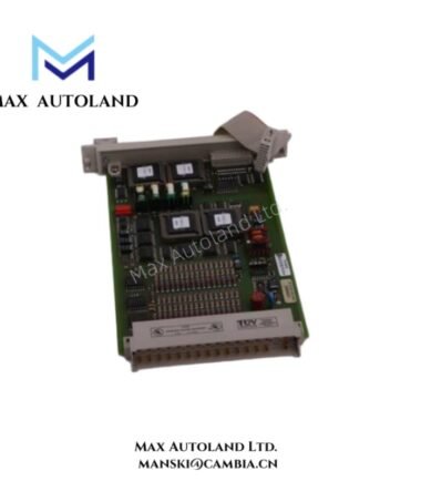
Overview
Hardware Specifications
| Parameter | Specification |
|---|---|
| Model | 10101/2/1 |
| Spare Model | 11000 DI-FS |
| Brand | Honeywell |
| Product Type | Digital Input Module |
| Origin | USA |
| Weight | 0.1 kg |
| Dimensions | 2 x 19 x 12.9 cm (estimated shipping size) |
| Operating Temp | Not specified |
| Power Consumption | 5 VDC: 8 mA; 24 VDC internal: 110 mA; 24 VDC external: 110 mA (input currents as supplied) |
| Number of Input Channels | 16 |
| Nominal Input Voltage | 24 VDC |
| Maximum Input Voltage | 36 VDC |
| Input Current | 7 mA at 24 VDC |
| Input HIGH Threshold | Greater than 15 VDC |
| Input LOW Threshold | Less than 9 VDC, with input current below 2 mA |
| 5 VDC Ripple Content | Less than 0.5 V peak-to-peak at 0-360 Hz |
| Space Requirements | 4 TE, 3 HE (4 HP, 3U) |
| Approvals | CE, TÜV, UL |
| Tariff Code | 8537101190 |
Digital Input Thresholds and Electrical Characteristics
The 10101/2/1 evaluates discrete DC input signals using defined voltage thresholds. An input voltage above 15 VDC represents the specified HIGH condition, while a voltage below 9 VDC represents the specified LOW condition when the input current remains below 2 mA. The region between these thresholds should be treated as an undefined transition range unless the applicable hardware documentation specifies otherwise.
The maximum stated input voltage is 36 VDC. Verify the field signal voltage and common-reference arrangement before connecting external circuits. The stated 5 VDC ripple limit is less than 0.5 V peak-to-peak over the specified 0-360 Hz range.
Frequently Asked Questions
Q: How many digital input channels does the Honeywell 10101/2/1 support?
A: The module supports 16 digital input channels, with a nominal input voltage of 24 VDC.
Q: What are the specified HIGH and LOW input thresholds?
A: HIGH is greater than 15 VDC. LOW is less than 9 VDC with input current below 2 mA. The interval between these thresholds is not defined as a valid logic state by the supplied specifications.
Q: What power supply requirements must be checked before installation?
A: Check the stated 5 VDC and 24 VDC supply requirements, the internal and external 24 VDC input-current figures, and the 5 VDC ripple limit. Confirm the exact supply connections and current requirements against the manufacturer’s installation documentation.
Field Installation Guidelines
- Verify the module identification and rack compatibility against the applicable Honeywell system documentation before installation.
- Confirm the required 5 VDC and 24 VDC supply connections and observe the specified polarity.
- Check each field input signal against the 36 VDC maximum input rating and the documented logic thresholds.
- Route digital signal wiring separately from high-voltage switching and motor power cables where practical to reduce electrical interference.
- Apply the system’s documented grounding and shielding practices. Do not connect signal commons or cable shields to unverified terminals.
- Inspect terminal connections and verify input states during commissioning. Use the manufacturer’s wiring diagram to confirm channel assignments and permitted external circuit arrangements.
- Do not assume hot-swap support or redundant operation without confirmation in the relevant system manual



Reviews
There are no reviews yet.