

Overview
Specifications
| ParameterSpecification | |
| Model | 330103-00-11-10-02-05 |
| Brand | Bently Nevada |
| Origin | Not specified |
| Weight | Not specified |
| Dimensions | 8 mm probe form factor (standard series geometry) |
| Operating Temp | Not specified |
| Power Consumption | Powered via Proximitor driver loop (system dependent) |
| Measurement Principle | Eddy-current displacement transduction |
| Nominal Probe Size | 8 mm |
| Output Interface | Proximitor-compatible analog voltage signal |
Eddy-Current Probe Scaling and Gap Voltage Behavior (TSI Characteristics)
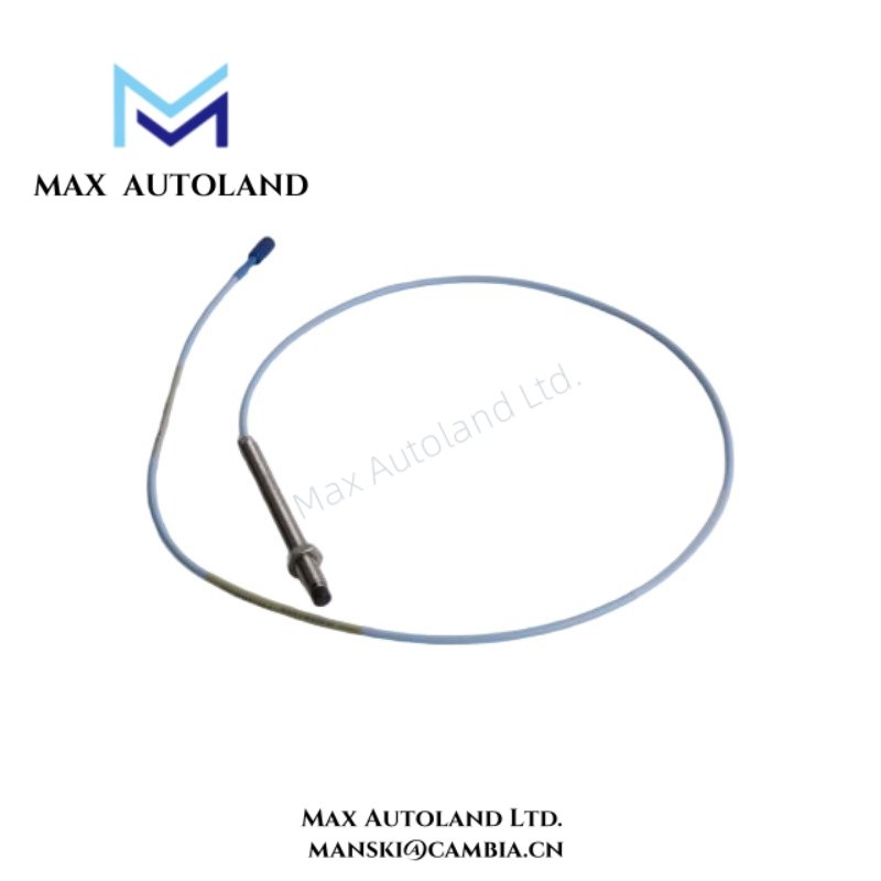
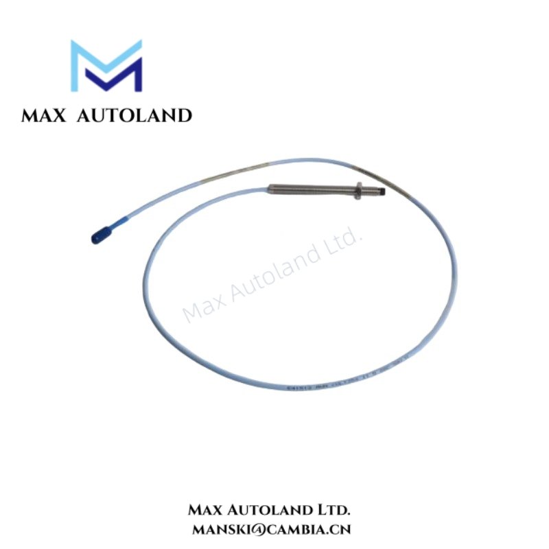
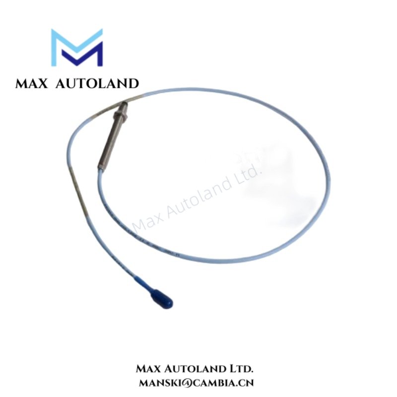
The Bently Nevada 3300 XL probe family operates through eddy-current field interaction between the probe tip and the conductive shaft surface. As the probe approaches the target, displacement variation directly modifies coil impedance, and this change produces a calibrated voltage response at the Proximitor output stage.
In practice, scaling behavior follows factory calibration curves, where axial gap changes map to a linearized voltage output. During commissioning activities, engineers commonly reference gap voltage validation against approximately -10 VDC bias conditions at defined mechanical clearance points. Across the full operating range, the system maintains signal linearity to support rotor dynamic analysis functions.
Additionally, cross-talk suppression relies on probe-coil shielding geometry and frequency-stable oscillator excitation. This design reduces interference between adjacent measurement channels, especially in dense multi-probe installations.
Suffix Breakdown & Model Matrix
No official publicly available suffix decomposition exists for 330103-00-11-10-02-05 beyond manufacturer configuration coding. Therefore, the ordering structure represents a factory-defined identifier that specifies probe type, cable length, connector style, and installation variant.
Frequently Asked Questions (FAQ)
Q: Can the 330103 probe be hot-swapped during system operation?
A: The probe itself remains passive; however, when the Proximitor loop stays energized, disconnection may trigger transient voltage spikes and temporary measurement loss until the loop stabilizes.
Q: What is the expected backplane or system loading impact of multiple probe channels?
A: The Proximitor driver module determines overall load. Each probe channel contributes to oscillator loading, and the system enforces defined channel density limits within the 3300 XL architecture.
Q: Is signal calibration dependent on field cable length?
A: Yes. Cable length and extension configuration influence phase and amplitude response. Therefore, system calibration must match the installed cable length to maintain accurate displacement-to-voltage conversion.
Field Installation Guidelines
Probe installation must maintain a rigid mechanical mounting reference relative to the monitored shaft or target surface. In addition, the probe face should align perpendicular to the rotor surface to preserve eddy-current field symmetry.
Installers should also maintain minimum spacing between adjacent probes to reduce electromagnetic coupling effects. Cable routing must follow shielded conduit practices, and technicians should apply single-point grounding to the coaxial shield to avoid ground loop formation.
Finally, connector interfaces require torque tightening according to manufacturer mechanical fit standards, while avoiding stress on the probe body. If installers violate the bending radius of extension cables, impedance characteristics may change, which can degrade measurement stability.




Reviews
There are no reviews yet.