


Overview
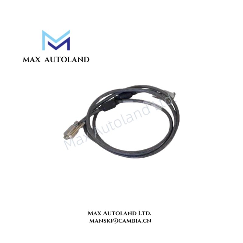
Configured for keyboard signal transmission in Honeywell operator workstation architectures, the Honeywell 51308058-100 (51308058-100 Keyboard Interface Cable) provides direct physical/electrical execution between the keyboard input assembly and workstation interface hardware within Honeywell TPS, TDC 3000, and Experion PKS systems. The cable is designed for low-voltage signal transport with shielded conductor construction intended to reduce susceptibility to electromagnetic interference during control system operation.
Suffix Breakdown & Model Matrix
The available source material identifies a single catalog number:
| Parameter | Specification |
|---|---|
| Full Model | 51308058-100 |
| Base Model | 51308058 |
| Variant Information | No official suffix differentiation provided in source data |
| Model Matrix | Not specified by manufacturer documentation provided |
Hardware Specifications
| Parameter | Specification |
|---|---|
| Model | 51308058-100 |
| Brand | Honeywell |
| Product Type | Keyboard Interface Cable |
| System Compatibility | Honeywell TDC 3000, TPS, Experion PKS |
| Conductor Type | Multi-strand copper conductors |
| Shielding | Aluminum foil and braided shield, greater than 85% coverage |
| Connector Type | Industrial molded connectors with locking mechanism |
| Jacket Material | Industrial-grade PVC or Polyurethane (PU) |
| Operating Temp | -20 degC to +75 degC |
| Storage Temp | -40 degC to +85 degC |
| Relative Humidity | 5 % to 95 % RH, non-condensing |
| Power Consumption | Passive cable, no independent power consumption |
| Signal Function | Keyboard and operator input signal transmission |
| EMI/RFI Protection | Dual-shielded cable construction |
Channel Isolation and Signal Integrity Characteristics
Within DCS workstation environments, low-level keyboard interface signals may be routed alongside power distribution, controller communication, and I/O cabling. The 51308058-100 cable utilizes foil and braid shielding to reduce external electromagnetic coupling into signal conductors. Proper shield termination practices support signal integrity and help minimize unwanted channel interaction generated by adjacent electrical circuits.
The cable functions as a passive transmission component and does not perform protocol conversion, signal conditioning, channel-to-channel isolation, or fieldbus communication. Electrical performance is determined primarily by conductor continuity, connector integrity, shielding effectiveness, and installation practices.
Frequently Asked Questions
Q: Does the 51308058-100 support hot replacement while the workstation is energized?
A: The cable itself is a passive component. Connector insertion or removal practices should follow the applicable Honeywell workstation maintenance procedures to prevent unintended operator interface interruptions.
Q: Does the cable require external power?
A: No. The 51308058-100 is a passive interface cable and contains no powered electronic circuitry.
Q: What installation factor most affects signal quality?
A: Shield continuity, correct connector engagement, proper strain relief, and separation from high-energy power conductors are the primary installation factors affecting signal transmission quality.
Field Installation Guidelines
- Verify connector orientation before insertion to prevent pin damage.
- Ensure connector locking mechanisms are fully engaged after installation.
- Maintain cable routing separate from high-voltage AC power conductors where practical.
- Avoid excessive bending, twisting, or tensile loading during installation.
- Preserve shield integrity throughout the cable run and follow site grounding practices for shield termination.
- Inspect connector housings periodically for mechanical wear, contamination, or looseness.
- During maintenance activities, verify continuity and connector condition before returning the workstation to service.





Reviews
There are no reviews yet.