


Overview
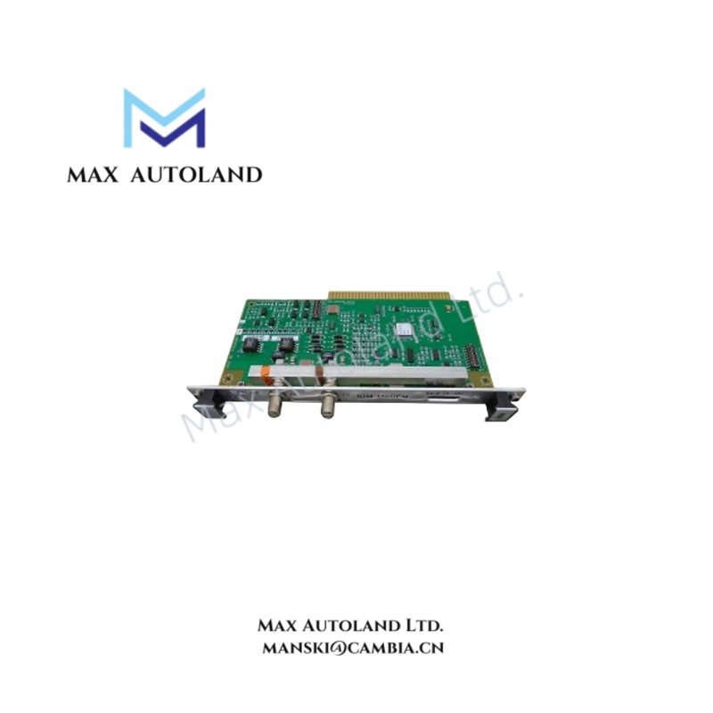
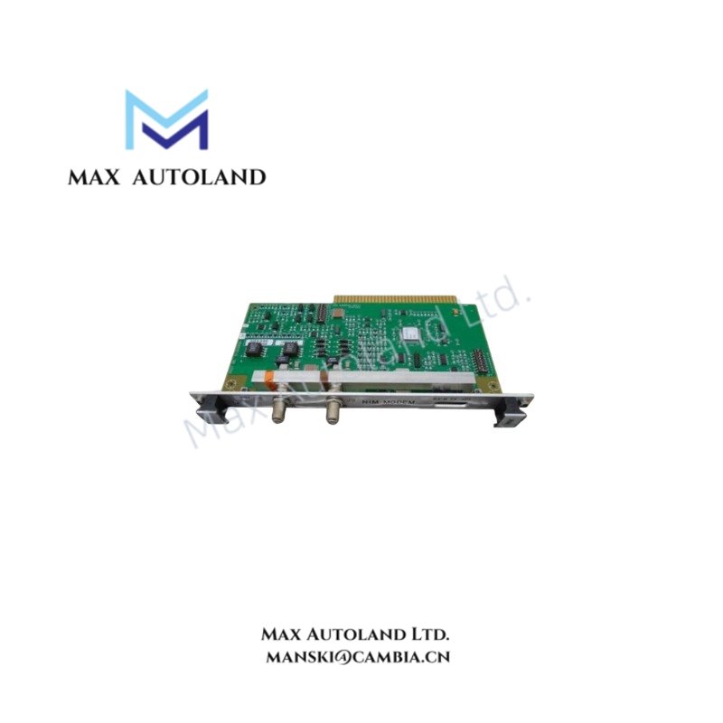
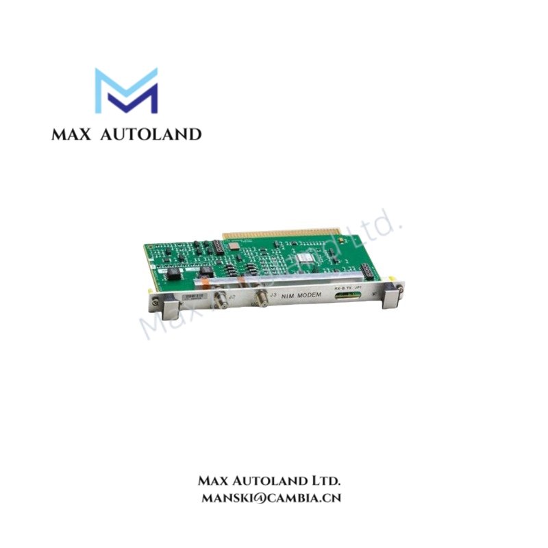
The Honeywell 51155967, also cataloged as the 51155967 Analog I/O Module, operates as a dedicated hardware component for analog signal acquisition and output execution within the TDC 3000 distributed control system network.
Hardware Specifications
| Parameter | Specification |
|---|---|
| Model Brand | Honeywell 51155967 |
| Origin | USA |
| Weight | 2.4 lbs (1089 g) |
| Dimensions | 8.3 x 6.3 x 3.2 in (211 x 160 x 81 mm) |
| Operating Temp | -40 to 85 degC |
| Storage Temp | -55 to 105 degC |
| Relative Humidity | 0% to 95% RH (non-condensing) |
| Power Consumption | 24 VDC nominal |
| Signal Type | Analog Input / Output |
| Signal Range | 4-20 mA |
| Channels | 32 |
| Accuracy | +/- 0.1% of full scale |
| Isolation | Channel-to-power circuitry isolation |
Channel-to-Channel Isolation and Loop Integrity
This module employs channel-to-power circuitry isolation to suppress ground loop currents and mitigate common-mode electrical noise on 4-20 mA analog loops. The design maintains signal integrity under high electromagnetic interference conditions typical of process control enclosures. No external galvanic isolators are required for standard TDC 3000 cabinet configurations.
Frequently Asked Questions
Q: Does the 51155967 support hot-swapping without system shutdown?
A: Yes, the module supports hot-swap replacement within TDC 3000 racks; however, proper electrostatic discharge precautions must be observed before extraction or insertion.
Q: What is the expected backplane current load for this module?
A: The module operates at a nominal 24 VDC input; exact backplane current draw depends on active channel loading but remains within TDC 3000 rack power budgets.
Q: Are there firmware dependencies affecting compatibility with newer TDC 3000 I/O expanders?
A: Firmware revisions must match the host controller’s I/O database configuration to ensure correct channel addressing and diagnostics.
Field Installation Guidelines
Mount the module directly into the designated TDC 3000 I/O slot using the supplied guide rails. Ensure all 4-20 mA field wiring shields are terminated to the cabinet ground bus to reduce EMI coupling. Verify torque specifications on terminal screws meet manufacturer standards to prevent contact resistance issues. Before energizing, confirm no cross-wiring exists between input and output channels to avoid loop excitation faults.




Reviews
There are no reviews yet.