
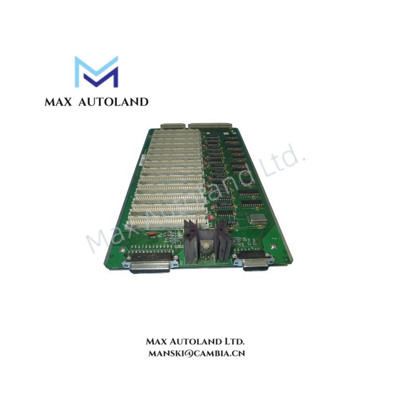
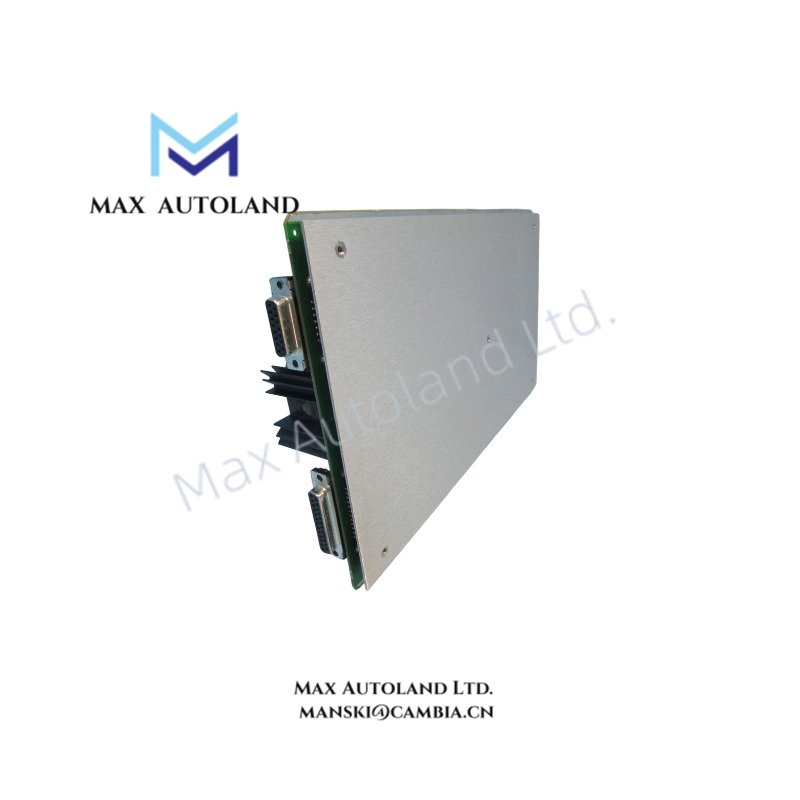
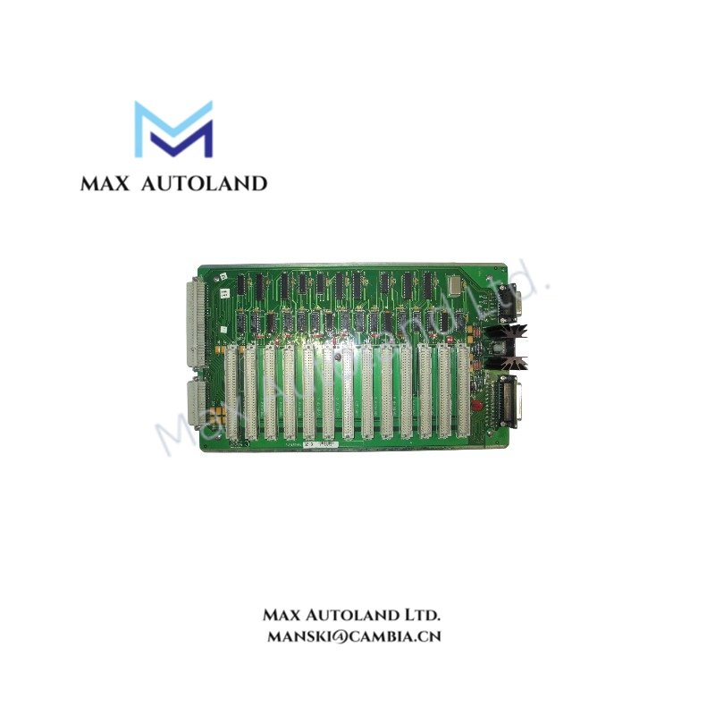

Overview
Suffix Breakdown & Model Matrix
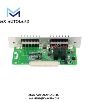
No validated manufacturer-documented suffix segmentation is defined for 105401-02. The “-02” identifier is treated as a configuration or revision index within the same base backplane hardware family. No functional partitioning logic is assumed beyond revision tracking.
Hardware Specifications
| Parameter | Specification |
|---|---|
| Model | 105401-02 |
| Brand | Bently Nevada |
| Origin | USA (GE / Bently Nevada manufacturing ecosystem) |
| Operating Temp | Industrial grade (system dependent) |
| Power Consumption | Backplane dependent load (rack supplied) |
| Function | Sampler backplane for TDXnet transient data system |
| Data Architecture | Multi-slot rack backplane communication |
| Interface Type | System backplane electrical bus |
Mechanical Monitoring Backplane Signal Coordination (Bently Nevada TSI Domain)
The module participates in TSI-level signal orchestration where eddy-current probe scaling chains are referenced upstream in connected monitoring modules. In typical system implementation, gap voltage validation workflows operate around negative bias reference ranges (e.g., -10 VDC target alignment at probe conditioning stages), while the backplane maintains deterministic routing integrity for conditioned signals. Rotor dynamics datasets derived from connected channels are buffered through the sampler architecture, with cross-talk suppression managed at system segmentation level rather than at the backplane copper plane itself.
Frequently Asked Questions (FAQ)
Q: Does the 105401-02 support hot-swap operation within a powered rack?
A: Hot-swap behavior is determined by the TDXnet chassis design. The backplane itself provides passive interconnect; insertion under load depends on system-level design constraints.
Q: What is the backplane contribution to channel isolation?
A: Channel-to-channel isolation is primarily enforced at the acquisition module level. The backplane provides routing paths without adding active isolation elements.
Q: How does the board handle transient buffer synchronization?
A: Buffer synchronization is executed by upstream sampler/controller logic; the backplane distributes timing and data lines without independent processing.
Field Installation Guidelines
Ensure the rack is fully de-energized prior to insertion of the 105401-02 module. Align edge connectors uniformly to avoid mechanical stress on backplane pins. Maintain controlled torque during chassis mounting to prevent PCB flex. Shield grounding continuity must be maintained across rack frame bonding points. Signal cabling routed to adjacent modules should preserve separation between high-speed data lines and low-level vibration inputs to minimize induced coupling. Do not introduce contamination or conductive debris into backplane connector slots during servicing.




Reviews
There are no reviews yet.