
Overview
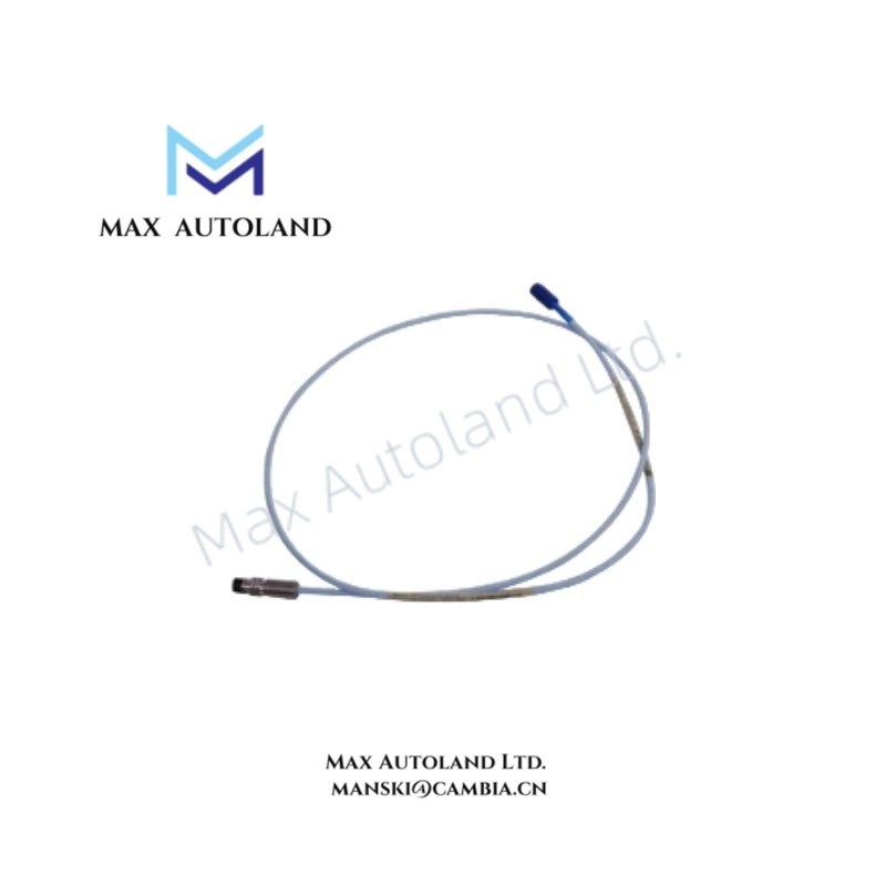
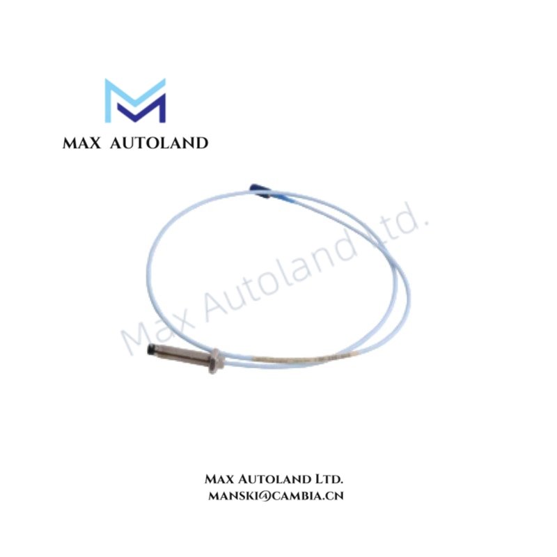
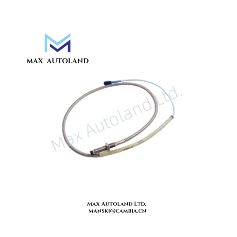
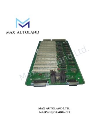
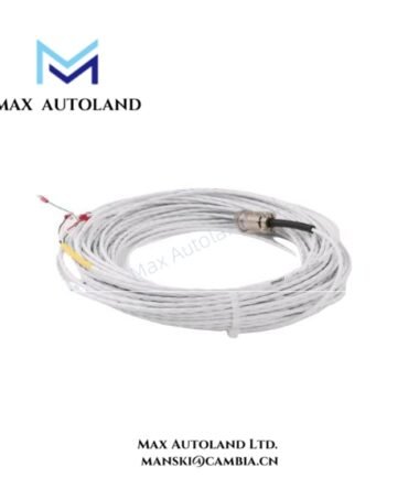
Configured for intra-rack signal transmission and backplane-to-module interconnection in Bently Nevada 3500/3300 architectures, the Bently Nevada 80705-01 (80705-01 internal cable assembly / interconnect harness) provides direct physical/electrical execution.
Suffix Breakdown & Model Matrix
No validated manufacturer-published suffix segmentation is defined for 80705-01. The part is treated as a single-order internal assembly without documented variant hierarchy.
Hardware Specifications
| Parameter | Specification |
|---|---|
| Model | 80705-01 |
| Brand | Bently Nevada |
| Operating Temp | -20 deg C to +70 deg C (typical industrial enclosure range) |
| Power Consumption | Passive component (no direct power draw) |
| Component Type | Internal cable assembly / interconnect harness |
| Application | 3500 / 3300 Series monitoring rack interconnect |
| Conductor Material | Tinned copper or silver-plated copper (application dependent) |
| Shielding | Braided or foil shield with drain wire |
| Insulation | Flame-retardant / LSZH or PTFE (application dependent) |
| Connector Interface | Multi-pin or coaxial terminated harness |
Eddy-Current Signal Integrity and Cross-Talk Suppression (Bently Nevada TSI Domain)
In Bently Nevada turbine supervisory instrumentation (TSI) systems, the 80705-01 harness is positioned within signal chains carrying eddy-current proximity probe outputs and seismic transducer signals. The assembly maintains controlled impedance paths between probe drivers and monitoring modules, limiting degradation of low-level AC carrier signals used for gap measurement scaling.
Cross-talk suppression is achieved through braided shielding continuity and drain wire termination referenced to rack ground potential. This structure reduces interference between adjacent channels carrying rotor dynamic vibration signals. In systems calibrated for gap voltage validation (commonly referenced around -10 VDC probe linear range limits), consistent shielding integrity directly affects demodulated displacement accuracy and phase stability in rotating machinery analysis.
Frequently Asked Questions (FAQ)
Q: Does the 80705-01 support hot-swap during system operation in 3500 racks?
A: It is a passive interconnect assembly. Hot-swap behavior depends on the connected module architecture; mechanical disconnection under energized conditions may introduce transient signal loss.
Q: What is the shielding termination requirement for this harness?
A: Shield continuity is typically terminated at rack ground or designated signal ground reference point to maintain EMI suppression and prevent floating shield conditions.
Q: Does the cable introduce measurable delay in vibration signal transmission?
A: Signal propagation delay is negligible due to short intra-rack length; electrical performance impact is dominated by shielding quality and connector contact resistance.
Field Installation Guidelines
The harness shall be installed within designated 3500 or 3300 rack cable routing channels. Bending radius must be maintained according to standard multi-core shielded cable handling practice to avoid conductor deformation or impedance discontinuity.
Shield drain wire must be terminated at a single grounding reference point to prevent ground loop formation. Routing should avoid parallel alignment with high-current backplane or switching power conductors to minimize induced EMI coupling.
Connector seating must be fully engaged with positive mechanical lock verified prior to system energization. Visual inspection of shielding continuity and insulation integrity is required before commissioning.






Reviews
There are no reviews yet.