
Overview
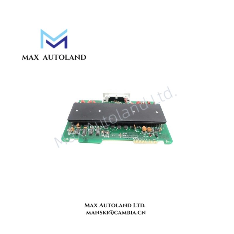
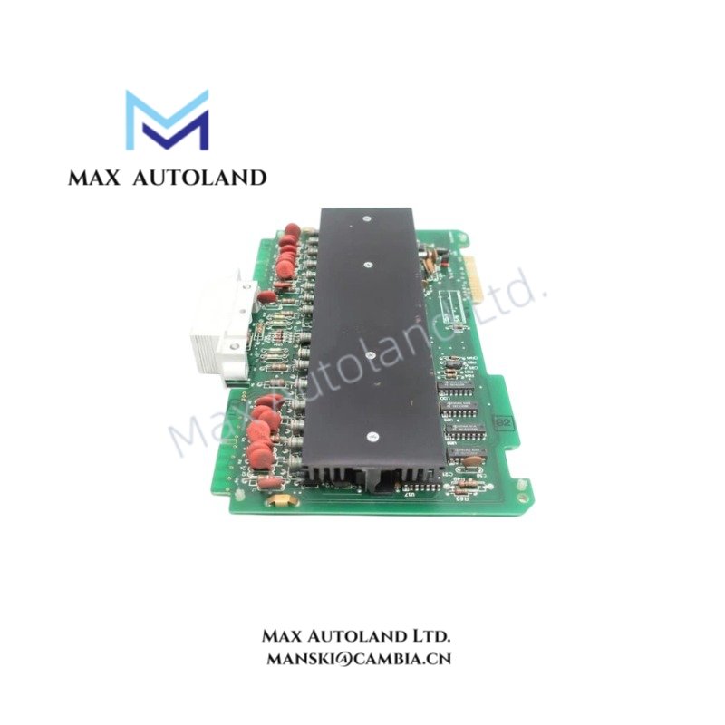
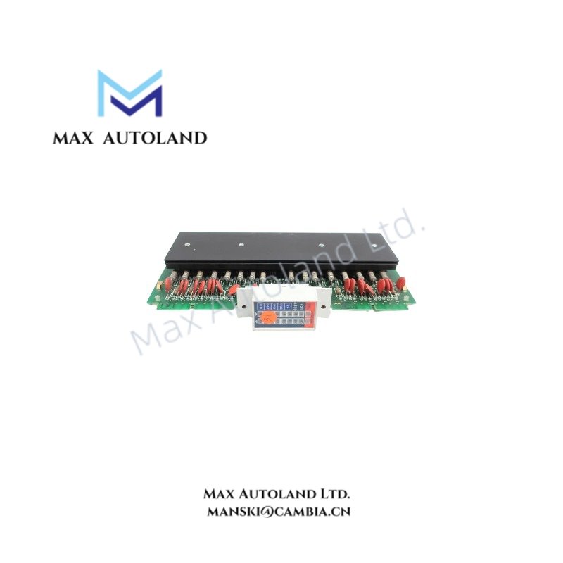
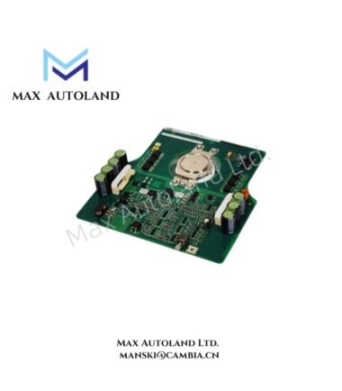
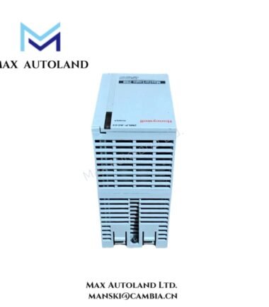
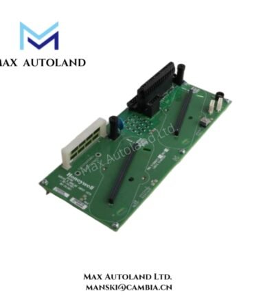
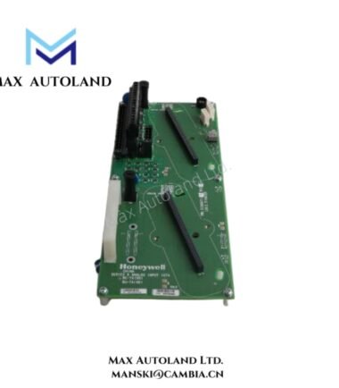
Configured for driving external 24 VDC discrete field loads in Honeywell 620 series controller platforms, the Honeywell 621-6550 (621-6550 Digital Output Module) provides direct physical/electrical execution. The hardware component manages the switching states of up to 16 independent sourcing outputs based on command signals processed across the system backplane.
Hardware Specifications
| Parameter | Specification |
|---|---|
| Model Brand | Honeywell |
| Module Type | Digital Output Module |
| Channel Density | 16 points |
| Output Type | Sourcing (Source Output) |
| Nominal Operating Voltage | 24 VDC |
| Alternate Part Number | 6216550 |
| Common Typographical Error | 621-655O |
| Origin | United States |
| Weight | 0.6 kg |
| Dimensions | 20.3 cm x 5.1 cm x 25.4 cm |
| Operating Temp | 0 to 60 degC |
| Power Consumption | Internal backplane draw dependent |
Channel-to-Channel Isolation Matrix
The hardware configuration features robust channel-to-channel isolation parameters designed to eliminate ground loop propagation across the 16 discrete output paths. Optical isolation barriers decouple the internal low-voltage system backplane logic from the 24 VDC field-side electrical circuits. This topology suppresses industrial transient noise and prevents localized electrical faults from compromising adjacent channels or the central processing infrastructure.
Frequently Asked Questions
Q: What is the electrical distinction of the sourcing output on the 621-6550 module?
A: The sourcing architecture implies that the module connects the 16 output points directly to the positive 24 VDC rail when an output point is energized, supplying current directly to the field device.
Q: Is hot-swapping supported for the 621-6550 module during active operations?
A: No, removal or insertion of the module while the chassis backplane is energized can cause electrical arcing or data corruption. Power down the rack assembly before executing replacement procedures.
Field Installation Guidelines
- Verify that the main chassis power supply and all external 24 VDC field power sources are completely de-energized prior to inserting the module into the designated slot.
- Align the printed circuit board with the chassis card guides and slide the unit inward until the backplane connectors seat firmly. Secure all mechanical retention screws.
- Route field wiring via dedicated wire ways segregated from high-voltage AC power lines to minimize electromagnetic interference.
- Ensure all shield wires are terminated at a single, low-impedance industrial earth ground point within the enclosure panel.






Reviews
There are no reviews yet.