
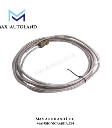
Overview
Suffix Breakdown & Model Matrix
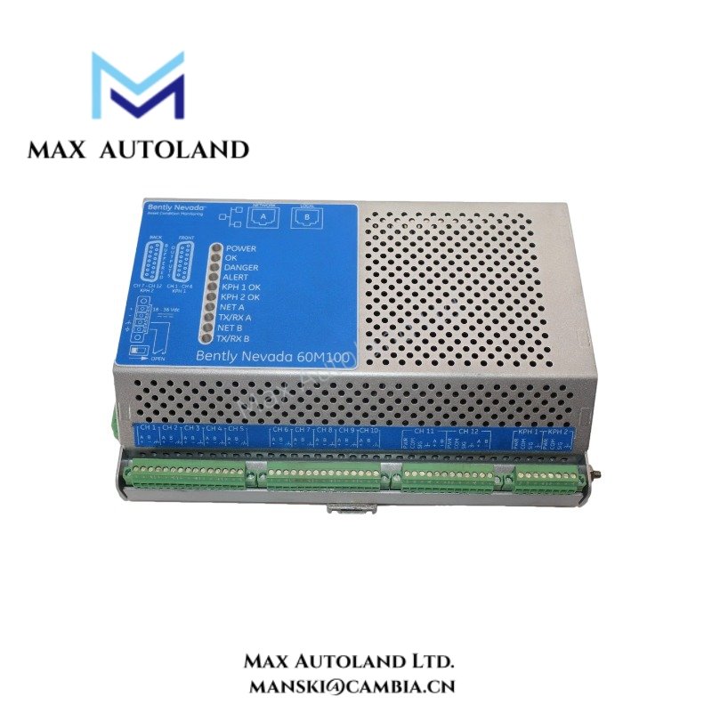
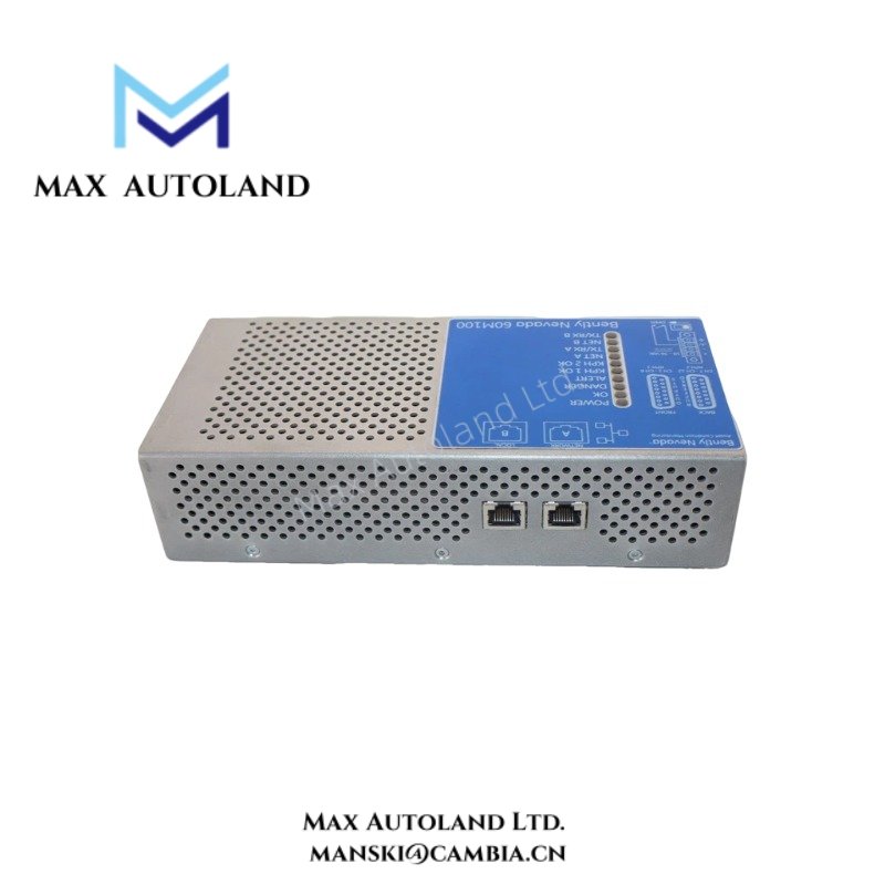
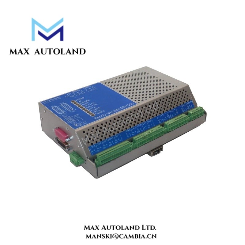
The supplied documentation identifies 60M100-00 as a fixed model designation within the 60M100 Condition Monitoring System platform. No additional suffix decomposition is explicitly defined in the provided source material.
Specifications
| ParameterSpecification | |
| Model | 60M100-00 |
| Brand | Bently Nevada |
| Origin | Baker Hughes / Bently Nevada product line |
| Product Family | 60M100 Condition Monitoring System |
| System Function | Condition monitoring and machinery diagnostic processing |
| Input Type | Dynamic machinery condition signals and monitoring data channels |
| Communication | System-level monitoring and data interface support |
| Weight | Not explicitly specified in provided data |
| Dimensions | Not explicitly specified in provided data |
| Operating Temp | Refer to manufacturer datasheet |
| Power Consumption | Refer to manufacturer datasheet |
| Mounting | Industrial control cabinet / monitoring system installation |
Rotor Dynamics Monitoring and Signal Scaling
The 60M100 platform operates within machinery protection and condition assessment environments where rotor behavior, vibration amplitude, and dynamic response require continuous observation. In eddy-current measurement chains, probe scaling influences displacement interpretation, waveform integrity, and shaft motion analysis.
Gap voltage verification remains a standard commissioning practice for proximity channels. Target bias validation near -10 VDC supports confirmation of probe positioning, transducer linear operating range, and acceptable shaft-to-probe spacing conditions.
Frequently Asked Questions
Q: Does the 60M100-00 support hot insertion during system operation?
A: The provided documentation does not explicitly define hot-swap capability. Installation and removal procedures should follow system shutdown and manufacturer maintenance practices.
Q: Why is gap voltage validation relevant in condition monitoring systems?
A: Gap voltage confirms correct probe target distance and sensor operating region. In Bently Nevada proximity systems, technicians commonly validate bias conditions near -10 VDC during setup.
Q: Can signal cable routing affect monitoring accuracy?
A: Yes. Dynamic signal wiring placed adjacent to high-current conductors or switching sources can introduce noise coupling, waveform distortion, or measurement instability.
Field Installation Guidelines
Maintain physical separation between transducer signal wiring and power conductors. Terminate cable shielding according to single-point grounding practices defined by plant instrumentation standards.
Verify connector seating, terminal torque, and channel identification before energizing the monitoring assembly. Avoid tight cable bends near transducer interfaces and communication ports.
Where proximity sensing channels exist within the monitoring topology, confirm probe gap response, polarity, and channel scaling before enabling alarm logic or automated machine evaluation functions.





Reviews
There are no reviews yet.