
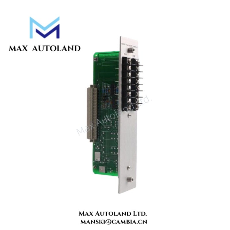
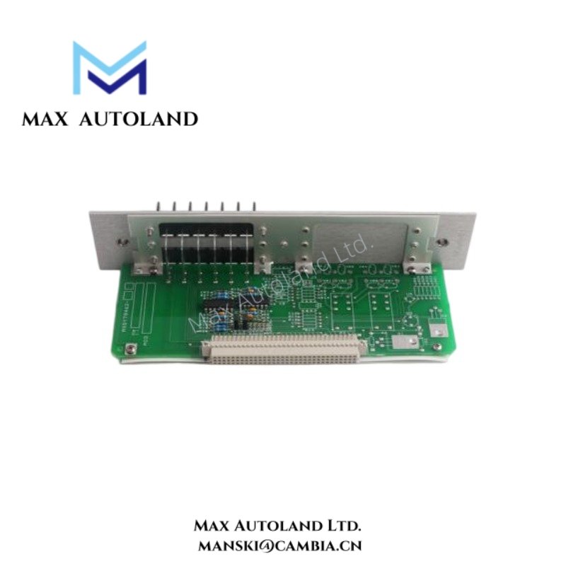
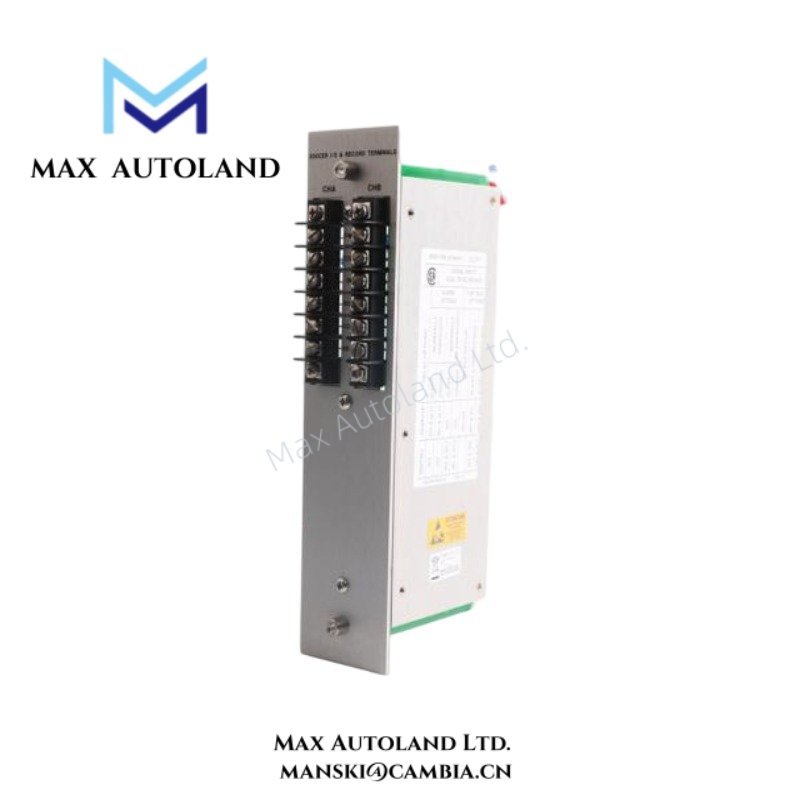
Overview
Suffix Breakdown & Model Matrix
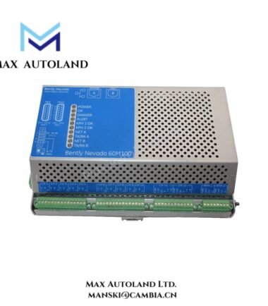
The available source material identifies 81544-01 as a fixed model configuration for the Signal Input / Alarm Output Transducer Module. No documented suffix matrix or ordering code decomposition is explicitly defined in the supplied references.
Specifications
| ParameterSpecification | |
| Model | 81544-01 |
| Brand | Bently Nevada |
| Origin | GE / Bently Nevada |
| Product Type | Signal Input Alarm Output Modules |
| Module Function | Signal acquisition and alarm output interfacing |
| Interface Type | Transducer input and terminal output handling |
| Signal Category | Monitoring transducer signal processing |
| Alarm Capability | Alarm output execution |
| Terminal Arrangement | Record terminal connectivity |
| Weight | Not specified in source data |
| Dimensions | Not specified in source data |
| Operating Temp | Refer to associated system environmental specifications |
| Power Consumption | Depends on installed system configuration |
Eddy-Current Probe Scaling and Rotor Dynamics Correlation
The 81544-01 operates in monitoring environments where transducer-derived signals support machinery condition assessment and alarm generation. Signal behavior depends on stable electrical routing between sensing elements and monitoring circuitry.
In systems using eddy-current proximity probes, displacement measurement follows calibrated probe scaling between target gap variation and output response. Commissioning procedures commonly include gap voltage validation near -10 VDC nominal targets.
Rotor dynamics evaluation may combine transducer inputs from shaft position, casing vibration, or process-related monitoring channels. Wiring discipline and channel separation reduce unintended interaction between measurement paths.
Frequently Asked Questions
Q: Does the 81544-01 include integrated relay hardware?
A: The referenced material identifies the module as a signal input and alarm output transducer interface. Relay configuration details should be verified against the associated system documentation for the installed variant.
Q: Can signal wiring and alarm conductors share the same cable route?
A: Shared routing is generally avoided. Low-level transducer wiring should remain separated from switched alarm conductors and external power wiring.
Q: Are shield termination practices required for module installation?
A: Yes. Shielded instrumentation wiring and controlled grounding practices help limit noise coupling into transducer signal paths.
Field Installation Guidelines
Verify terminal identification and conductor mapping before landing field wiring. Maintain labeling consistency between transducer inputs, alarm outputs, and record terminal points.
Separate signal cables from motor feeders, relay switching circuits, and AC distribution conductors. Use protected routing methods for instrumentation wiring.
Inspect conductor retention, terminal tightness, and shield continuity before energizing the monitoring assembly.
Where the module interfaces with external shutdown or annunciation circuits, confirm electrical compatibility and continuity using the applicable wiring documentation.


Reviews
There are no reviews yet.