
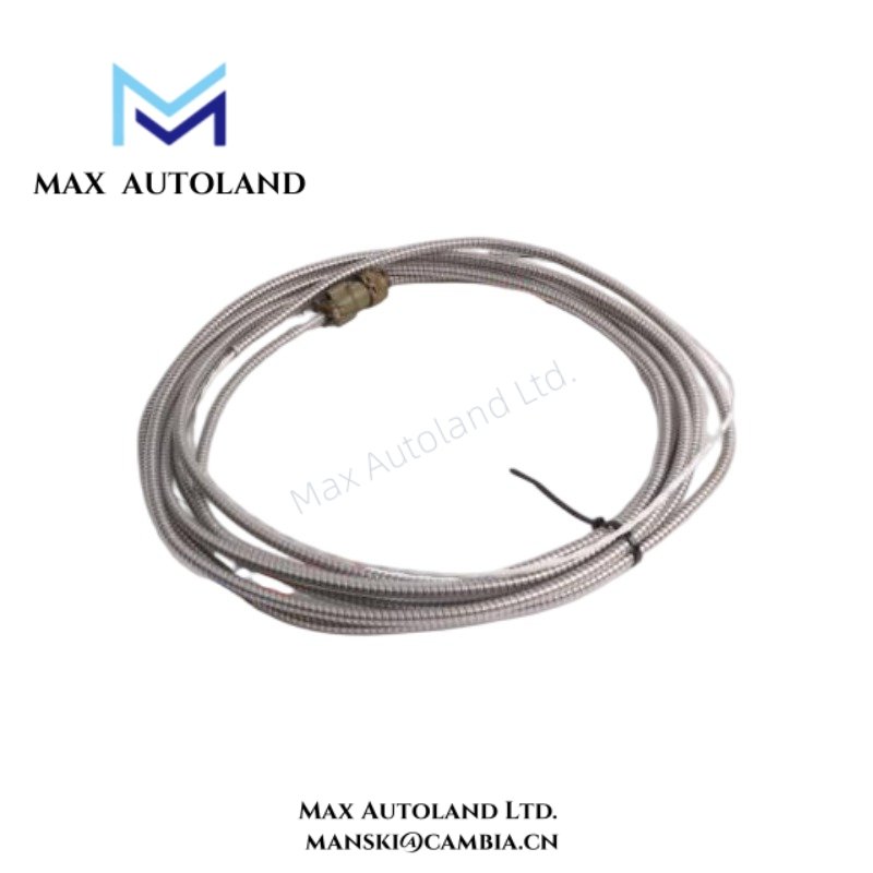
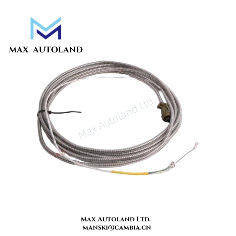
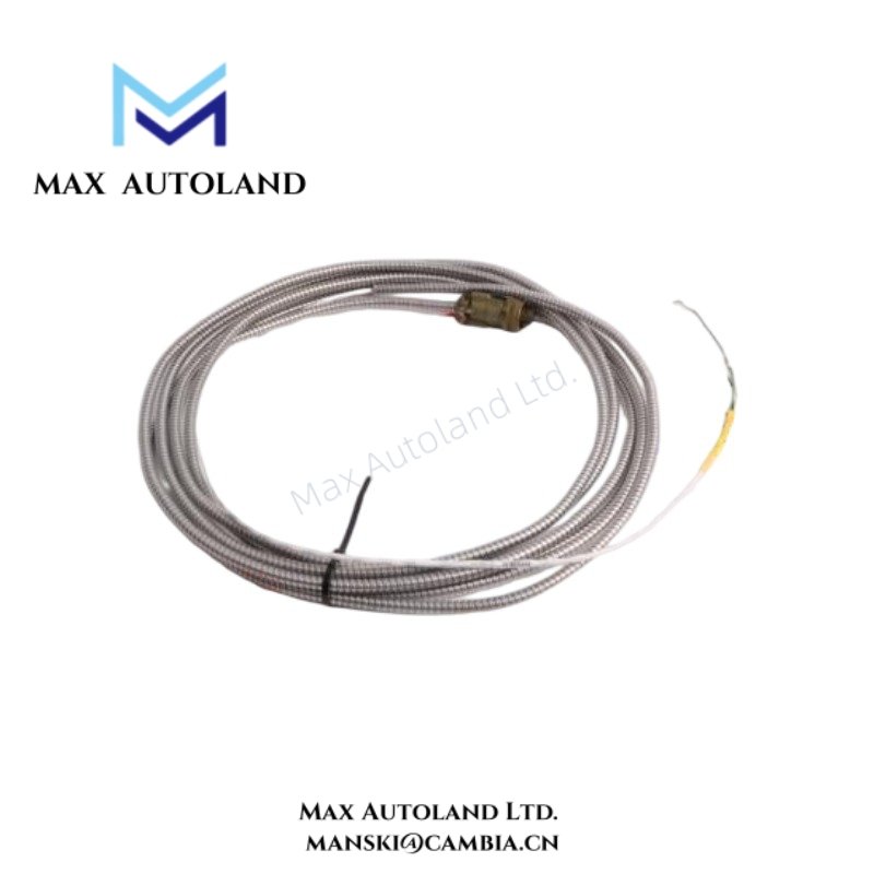
Overview
Specifications
| ParameterSpecification | |
| Model | 84661-20 |
| Brand | Bently Nevada |
| Origin | Baker Hughes / Bently Nevada product line |
| Product Family | Velomitor Interconnect Accessories |
| Cable Function | Sensor interconnection and signal transfer |
| Compatible System | Bently Nevada Velomitor monitoring architecture |
| Signal Type | Dynamic vibration / velocity sensor signal path |
| Connector Interface | Refer to manufacturer configuration data |
| Weight | Not explicitly specified in provided data |
| Dimensions | Length and physical dimensions per manufacturer configuration |
| Operating Temp | Refer to associated sensor and cable specifications |
| Power Consumption | Passive component; no independent power requirement |
Cross-Talk Suppression in Dynamic Sensor Wiring
Dynamic vibration monitoring circuits require controlled cable routing to minimize electromagnetic coupling between adjacent channels. In Velomitor installations, interconnect cable layout influences waveform integrity, noise rejection, and channel separation behavior.
Cross-talk suppression practices include shield continuity management, separation from motor feeder conductors, and avoidance of parallel routing beside switching power cables. Signal quality degradation can affect vibration trending and diagnostic interpretation within rotating machinery monitoring systems.
Frequently Asked Questions
Q: Does the 84661-20 cable require an external power connection?
A: No. The cable functions as a passive signal interconnect assembly and does not consume independent electrical power.
Q: Can this interconnect cable be routed in the same tray as high-voltage conductors?
A: Industrial practice recommends separation between low-level vibration signal wiring and high-energy power circuits to reduce induced electrical noise.
Q: Does cable shielding affect measurement stability?
A: Yes. Shield termination and grounding practice influence noise immunity, signal reference behavior, and susceptibility to electromagnetic interference.
Field Installation Guidelines
Install the cable with controlled bend radius and avoid mechanical strain near connectors or sensor interfaces. Maintain physical segregation from VFD output cables, contactor wiring, and high-current conductors.
Inspect connector engagement before system energization. Preserve shield continuity according to plant instrumentation grounding standards. Do not create unintended multiple shield ground points unless explicitly defined by the system documentation.
When connected to Velomitor measurement chains, verify channel continuity and confirm expected monitoring response after installation.





Reviews
There are no reviews yet.