
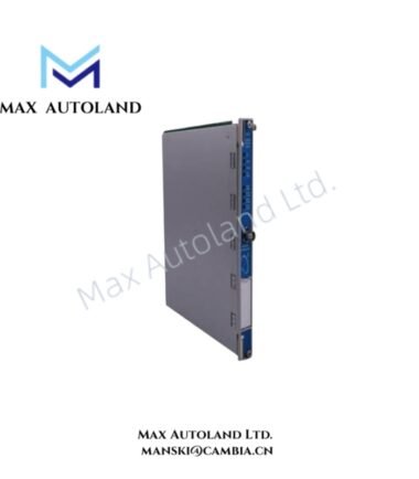
Overview
Hardware Specifications
| Parameter | Specification |
|---|---|
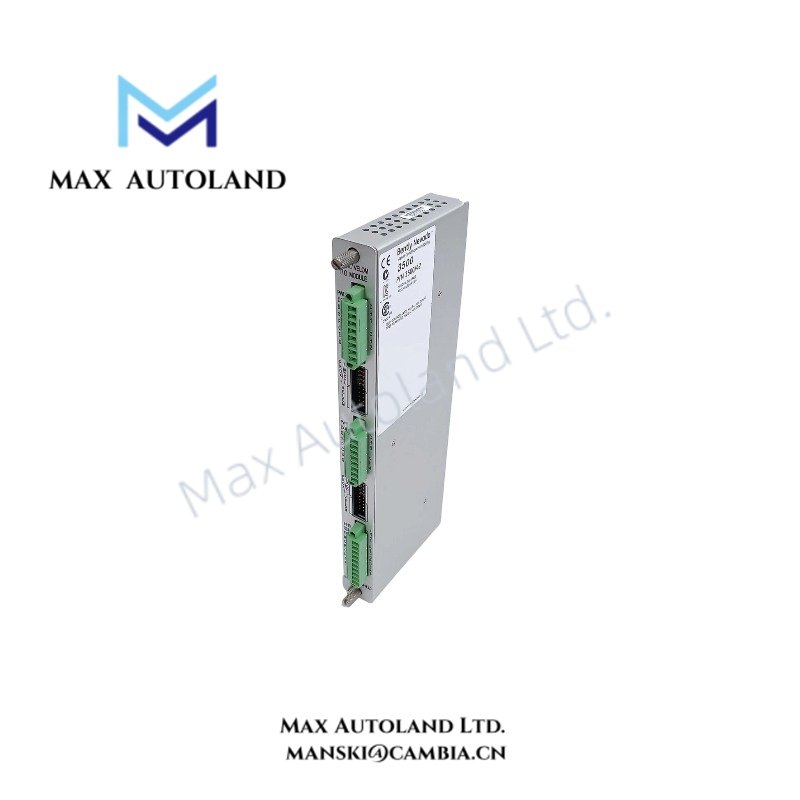
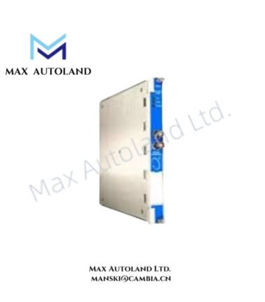
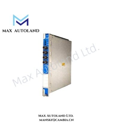
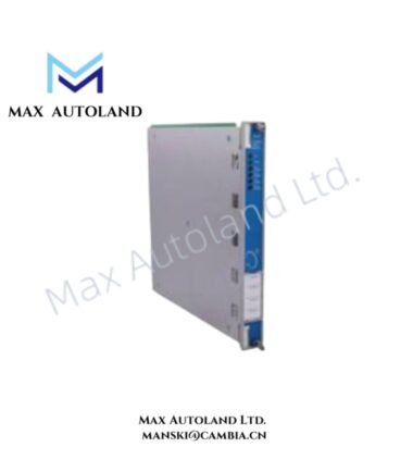
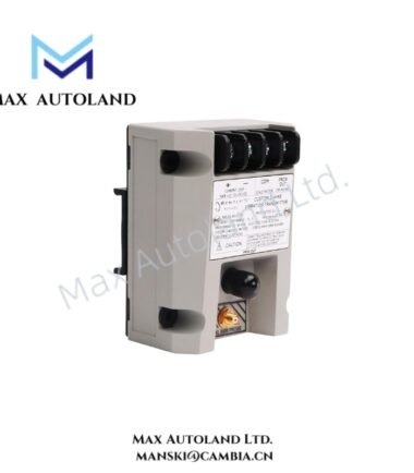
| Model | 3500/42M Proximitor/Seismic Monitor |
| Part Number | 138700-01 |
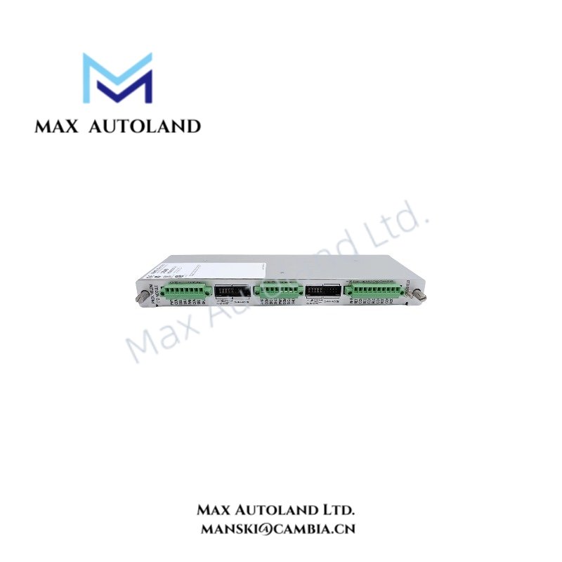
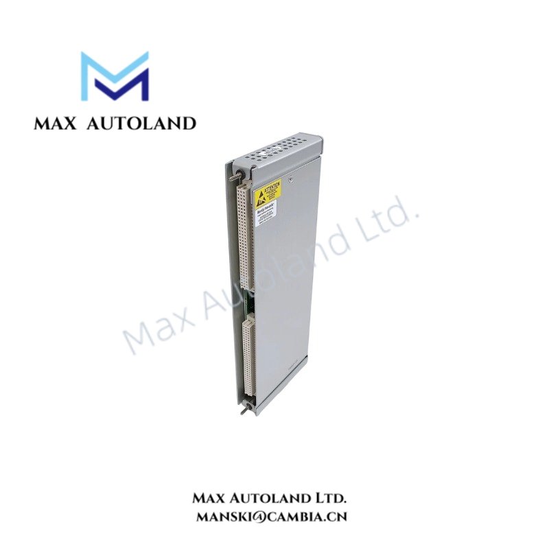
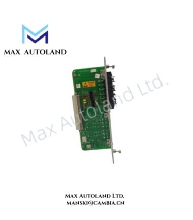
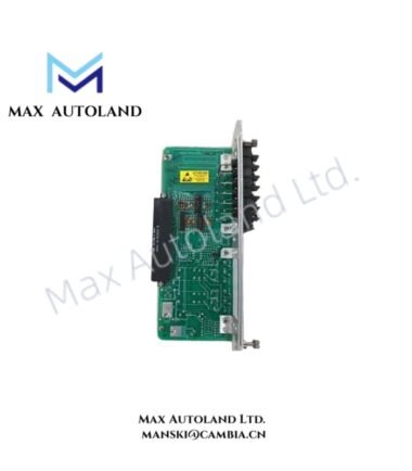
| Module Type | Shaft Absolute I/O Module with External Terminations |
| Brand | Bently Nevada |
| System | 3500 Series Machinery Protection System |
| Channels | 4 |
| Input Signal Types | Proximity, velocity, and acceleration transducers |
| Input Impedance | 10 kOhm typical for Proximitor and acceleration inputs |
| Transducer Power Supply | -24 VDC nominal |
| Recorder Outputs | +4 to +20 mA, proportional to monitor full-scale |
| Recorder Load Resistance | 0 to 600 Ohm |
| Buffered Transducer Outputs | Front-panel coaxial connectors, short-circuit protected |
| Buffered Output Impedance | 550 Ohm |
| External Termination | Required |
| Operating Temp | -30 deg C to +65 deg C |
| Storage Temp | -40 deg C to +85 deg C |
| Humidity | Up to 95%, non-condensing |
| Configuration | 3500 Rack Configuration Software |
Eddy-Current Probe Scaling and Gap Voltage
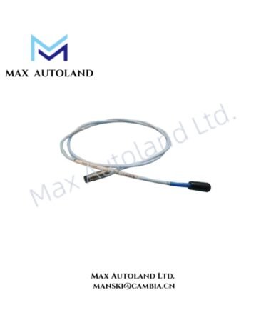
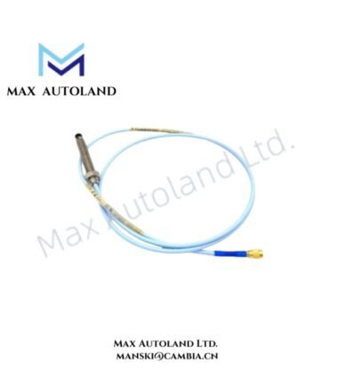
The 3500/42M accepts proximity transducer signals for measurements such as radial vibration and thrust position. For eddy-current probe systems, technicians should verify probe gap voltage before commissioning the monitor channel. A -10 VDC target is a commonly used reference condition for Bently Nevada proximity probe installation and calibration.
The signal path must maintain the specified probe polarity and wiring arrangement. Therefore, technicians should verify the transducer output, cable shield arrangement, and monitor channel assignment before applying alarm limits. Correct probe scaling also ensures that vibration and position values correspond to the configured engineering units.
Frequently Asked Questions
Q: What does Part Number 138700-01 identify?
A: Part Number 138700-01 identifies the Shaft Absolute I/O Module with External Terminations associated with the 3500/42M monitoring function.
Q: What input transducers can the 3500/42M accept?
A: The supplied data specifies compatibility with proximity, velocity, and acceleration transducers. The applicable signal type depends on the configured monitoring channel.
Q: What recorder output does the module provide?
A: The recorder output provides +4 to +20 mA proportional to monitor full-scale and supports a stated load range of 0 to 600 Ohm.
Field Installation Guidelines
- Install the I/O module in the specified 3500 rack position and verify the rack configuration before energizing the system.
- Use the required external termination hardware for Part Number 138700-01.
- Keep transducer signal wiring separated from high-voltage power conductors and high-current switching circuits.
- Maintain correct signal polarity and channel identification throughout the field wiring path.
- Terminate cable shields according to the approved 3500 system wiring practice and plant grounding specification.
- Verify proximity probe gap voltage before enabling vibration or position alarm functions.
- Confirm the transducer type and scaling configuration in the 3500 Rack Configuration Software.
- Check recorder output polarity and loop loading before connecting external monitoring equipment.
- Inspect coaxial buffered outputs for correct channel assignment before connecting diagnostic equipment.
- Verify environmental conditions against the specified -30 deg C to +65 deg C operating range and maximum 95% non-condensing humidity.


Reviews
There are no reviews yet.