
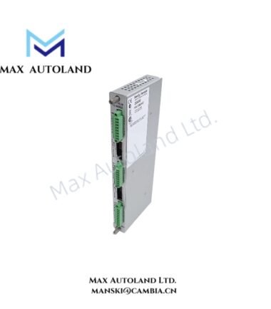
Overview
Hardware Specifications
| Parameter | Specification |
|---|---|
| Model | 3500/94 |
| Part Number | 161264-01 |
| Brand | Bently Nevada |
| Manufacturer | Bently Nevada (Baker Hughes) |
| Product Series | 3500 Machinery Protection System |
| Component Type | Industrial DC Power Supply |
| Primary Application | 3500/94M Display Router Box and RS Power Station |
| Compatibility | 3500/94 and 3500/94M VGA Display systems |
| Mounting | Industrial panel or cabinet installation |
| Output Function | DC power supply for display-related accessories |
3500 System Integration and DC Power Function
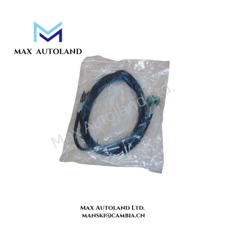
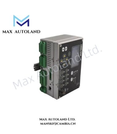
The 161264-01 operates as an auxiliary power component within the Bently Nevada 3500 display architecture. It supplies DC power to associated display routing and extension hardware rather than performing vibration signal acquisition.
Furthermore, the unit supports configurations involving the 3500/94 and 3500/94M VGA display systems. The specified application includes the Display Router Box and RS Power Station.
The 3500 system can process machinery monitoring signals through dedicated monitoring modules; however, this part number serves the DC power function for the associated display infrastructure. Therefore, eddy-current probe scaling, gap voltage validation, and rotor-dynamics calculations do not occur inside the 161264-01.
Frequently Asked Questions
Q: Is the 161264-01 a vibration monitoring input module?
A: No. The 161264-01 functions as an industrial DC power supply for the 3500 display-related hardware.
Q: Which 3500 display equipment does the 161264-01 support?
A: The supplied data identifies compatibility with the 3500/94 and 3500/94M VGA display systems, including the Display Router Box and RS Power Station.
Q: Does the supplied specification define the electrical output voltage or current rating?
A: No. The supplied data does not specify the DC output voltage, current capacity, power rating, or operating temperature range. These values should be verified against the applicable Bently Nevada documentation before installation.
Field Installation Guidelines
- Verify the complete part number, 161264-01, before installation.
- Confirm that the connected display equipment matches the supported 3500/94 or 3500/94M architecture.
- Install the power supply in the designated panel or cabinet location and maintain adequate physical clearance for wiring and service access.
- Route DC power wiring separately from high-current switching conductors and high-energy motor circuits where practical.
- Maintain correct polarity and terminal identification according to the applicable installation documentation.
- Bond the cabinet and protective earth according to the site electrical grounding standard.
- Keep signal and communication cables separated from power conductors to reduce electromagnetic coupling.
- Do not apply an unspecified input or output voltage. Confirm electrical ratings from the equipment documentation before energizing the circuit.
- Inspect connectors and wiring for mechanical damage, loose terminations, or insulation defects before commissioning.
- After installation, verify DC power availability at the connected display equipment before placing the 3500 display system into service.



Reviews
There are no reviews yet.